
Intelligent detection device for real-time static load test of pile foundation

An intelligent detection and static load technology, which is applied in the testing of infrastructure, infrastructure engineering, construction, etc., can solve the problems of variable detection methods, potential safety hazards, and structural instability, and achieve the effect of simplifying the construction process.

Inactive Publication Date: 2022-05-31
JIANGSU CHENGGONG CONSTR TECH
View PDF5 Cites 2 Cited by
  • Summary
  • Abstract
  • Description
  • Claims
  • Application Information

AI Technical Summary

Problems solved by technology

[0002] When the static load test of the pile foundation is carried out, the conventional detection method needs to use a large number of prefabricated concrete beams to exert pressure on the pile foundation. The preparation before the test takes a lot of time, and the accumulated structure of a large number of prefabricated concrete beams is unstable. It is necessary to enter the detection area, and there are potential safety hazards. At the same time, there are variables in the conventional detection method, which cannot guarantee the same pressure on each pile foundation to be tested, which has a certain impact on the accuracy of the detection results.

Method used


Image

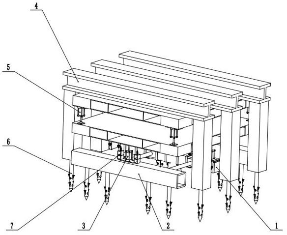
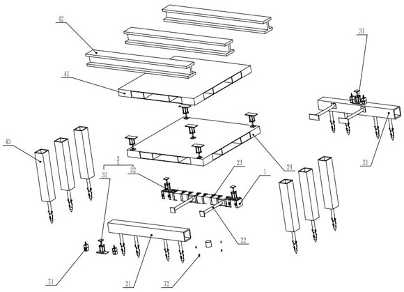
  • Intelligent detection device for real-time static load test of pile foundation
  • Intelligent detection device for real-time static load test of pile foundation
  • Intelligent detection device for real-time static load test of pile foundation

Examples


Embodiment Construction

[0016] The present invention will be further described below in conjunction with the accompanying drawings. The following examples are only used to illustrate the technical solution of the present invention more clearly, but not to limit the protection scope of the present invention.

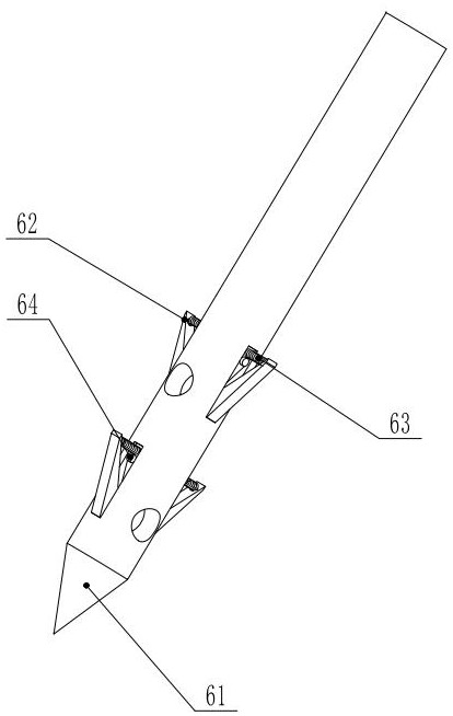
[0017] see Figure 1-6 , the present invention provides a technical solution: a pile foundation real-time static load test intelligent detection device, including a concrete beam 1, a reverse thrust steel structure 2, a reverse thrust cylinder group 3, a downward pressure steel structure 4, a downward pressure cylinder group 5, Ground hook 6, signal feedback unit 7. The concrete beam 1 is centrally placed above the pile foundation 8, and the pressure of the superstructure plays a role of fixing, and at the same time, the concrete beam 1 plays a role of dispersing the pressure, preventing the detection result error caused by the pressure being concentrated in a limited area; the reverse thrust o...


PUM


Abstract

The invention relates to a pile foundation static load test detection device, in particular to a pile foundation real-time static load test intelligent detection device which is characterized in that a large number of steel structures are used for replacing traditional concrete beams in a main body, so that the lightweight of the detection device can be realized, the preparation time of detection conditions can be shortened, the real-time return of detection data can be realized, and the intelligentization of the detection process can be realized; comprising a concrete beam, a reverse pushing steel structure, a reverse pushing oil cylinder set, a downward pressing steel structure, a downward pressing oil cylinder set, a ground hook and a signal feedback unit. The ground hook comprises a ground hook body, steel claws, a spring and an electromagnet, the front end of the ground hook body is of a pointed cone structure, the middle section of the ground hook body is provided with two mounting grooves perpendicular to each other, the two steel claws are hinged to each mounting groove, spring fixing grooves are formed in the side walls of the steel claws, one end of the spring is mounted in the spring fixing grooves in the side walls of the steel claws, and the other end of the spring is connected with the electromagnet. The other end of the ground hook body is fixed to the installation groove in the ground hook body, and an electromagnet is further installed in the installation groove in the ground hook body.

Description

technical field [0001] The invention relates to a pile foundation static load test detection device, in particular to a pile foundation real-time static load test intelligent detection device. Background technique [0002] When the static load test of the pile foundation is carried out, the conventional detection method needs to use a large number of prefabricated concrete beams to exert pressure on the pile foundation. It takes a lot of time to prepare before the test. The accumulated structure of a large number of prefabricated concrete beams is unstable. It is necessary to enter the detection area, and there are potential safety hazards. At the same time, there are variables in the conventional detection method, which cannot guarantee the same pressure on each pile foundation to be tested, which has a certain impact on the accuracy of the detection results. Contents of the invention [0003] In order to solve this problem, a real-time static load test intelligent detect...

Claims


Application Information

Patent Timeline
Patent Type & Authority Applications(China)
IPC IPC(8): E02D33/00
CPCE02D33/00
Inventor 黄小红金勇伟周凯姚坚超李银鹏严乐丽周余侯庆莹洪波涛
Owner JIANGSU CHENGGONG CONSTR TECH
Learn More