Heat exchange device

A technology of heat exchange device and heat exchange unit, which is applied in the direction of heating method, pipeline layout, household heating, etc., to ensure heat exchange efficiency and realize the effect of indoor air circulation

Pending Publication Date: 2022-06-03
PANASONIC ECOLOGY SYSTEMS GUANGDONG CO LTD
View PDF1 Cites 0 Cited by
  • Summary
  • Abstract
  • Description
  • Claims
  • Application Information

AI Technical Summary

Problems solved by technology

[0004] The present invention provides a heat exchange device capable of realizing indoor air circulation an

Method used


Image

  • Heat exchange device
  • Heat exchange device
  • Heat exchange device

Examples


Embodiment Construction

[0037] In order to make the purposes, technical solutions and advantages of the embodiments of the present invention clearer, the technical solutions in the embodiments of the present invention will be clearly and completely described below with reference to the accompanying drawings in the embodiments of the present invention. Obviously, the described embodiments These are some embodiments of the present invention, but not all embodiments. Based on the embodiments of the present invention, all other embodiments obtained by those of ordinary skill in the art without creative work fall within the protection scope of the present invention.

[0038]In the description of the present invention, it should be noted that the orientation or positional relationship indicated by the terms "upper", "lower", "top", "bottom", etc. refers to the orientation or positional relationship based on the installation state of the air-conditioning device . For example, the terms "upper" and "top" re...


PUM


Abstract

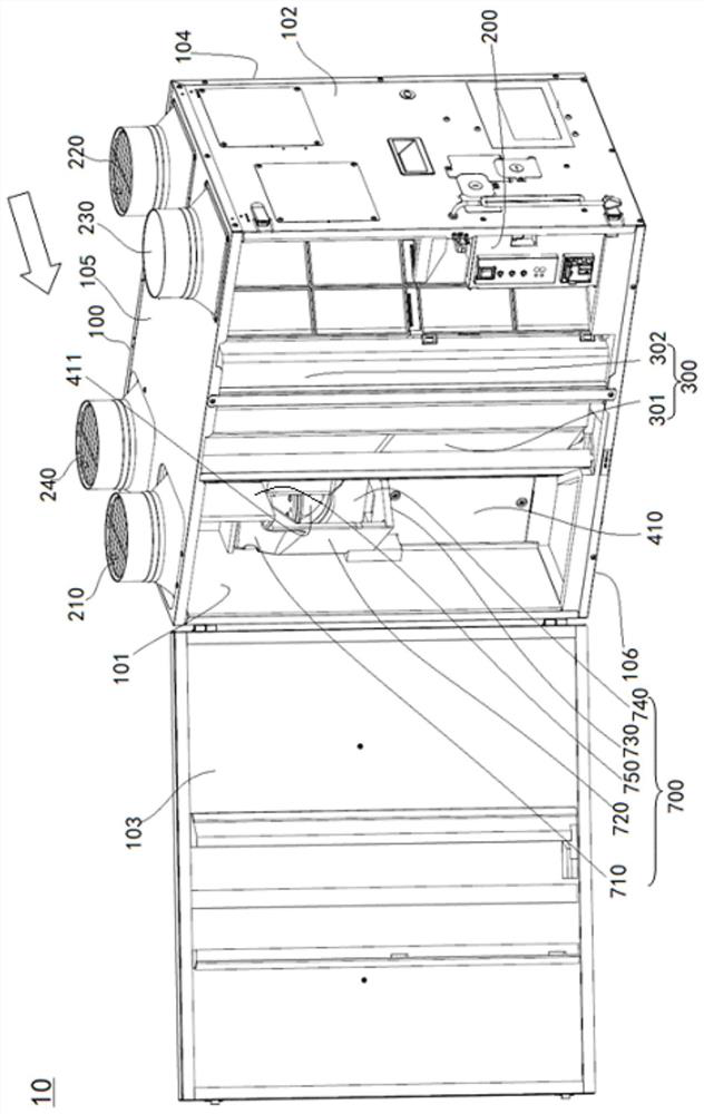
The invention provides a heat exchange device. The heat exchange device comprises a shell, an air supply air inlet space, an exhaust air inlet space, an air supply air outlet space and an exhaust air outlet space which are separated from one another are formed in the shell, and a first extending wall is arranged between the air supply air inlet space and the exhaust air outlet space; the heat exchange unit is arranged in the shell, the air supply air inlet space and the air supply air outlet space communicate with each other through the heat exchange unit to form an air supply air path, and the exhaust air inlet space and the exhaust air outlet space communicate with each other through the heat exchange unit to form an exhaust air path; wherein the air supply air path and the exhaust air path are subjected to heat exchange when passing through the heat exchange unit, a circulating air opening communicated with the air supply air inlet space and the exhaust air outlet space is formed in the first extension wall, and the circulating air opening can be selectively opened and closed. The heat exchange device can achieve indoor air circulation and ensure the heat exchange effect.

Description

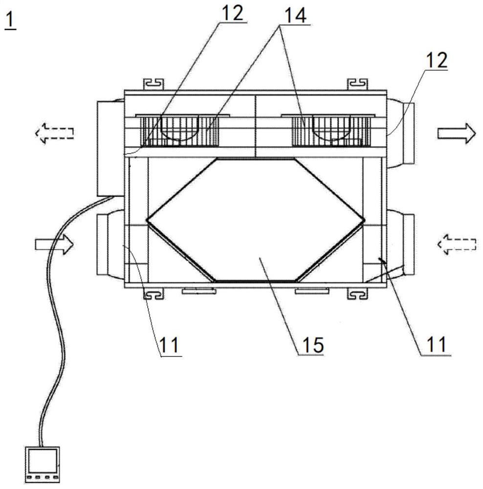
technical field [0001] The present invention relates to an air treatment device, in particular, to a heat exchange device. Background technique [0002] Chinese invention patent CN104236056B discloses a total heat exchanger 1, such as figure 1 As shown, the total heat exchanger 1 includes a casing 13 with an air inlet 11 and an air outlet 12 on both sides, respectively. A total heat exchange core 15 is set between the air inlet 11 and the two fans 14, and two heat exchange channels are formed in the total heat exchange core 15, which are independent of each other and can supply airflows to intersect each other, and the two heat exchange channels are formed. Both ends of the exchange channel are communicated with an air inlet 11 and an air outlet 12 respectively. like figure 1 As shown, the total heat exchanger 1 in the prior art is only formed with an outdoor fresh air channel and an indoor exhaust air channel which are respectively connected to an air inlet and an air o...

Claims


Application Information

Patent Timeline
IPC IPC(8): F24F7/08F24F12/00F24F11/89F24F13/02F24F13/20F24F13/30
CPCF24F7/08F24F12/006F24F11/89F24F13/02F24F13/20F24F13/30F24F2012/007Y02B30/56
Inventor 张钧杨镇泓关仕延
Owner PANASONIC ECOLOGY SYSTEMS GUANGDONG CO LTD
Why Eureka
Try Eureka