Energy accumulator and energy-saving system utilizing waste heat of engine tail gas

An energy-saving system and accumulator technology, which is applied to engine components, combustion engines, machines/engines, etc., and can solve problems such as the reduction of the working efficiency of accumulators

Active Publication Date: 2020-11-20
XUZHOU COLLEGE OF INDAL TECH
View PDF6 Cites 0 Cited by
  • Summary
  • Abstract
  • Description
  • Claims
  • Application Information

AI Technical Summary

Problems solved by technology

[0004] Aiming at the deficiencies in the prior art, the present invention provides an accumulator and an energy-saving system utilizing waste heat from engine exhaust. Reduce the impact of exhaust gas on the environment and improve the working efficiency of the accumulator

Method used


Image

  • Energy accumulator and energy-saving system utilizing waste heat of engine tail gas
  • Energy accumulator and energy-saving system utilizing waste heat of engine tail gas
  • Energy accumulator and energy-saving system utilizing waste heat of engine tail gas

Examples


Embodiment Construction

[0023] The present invention will be further described below in conjunction with accompanying drawing.

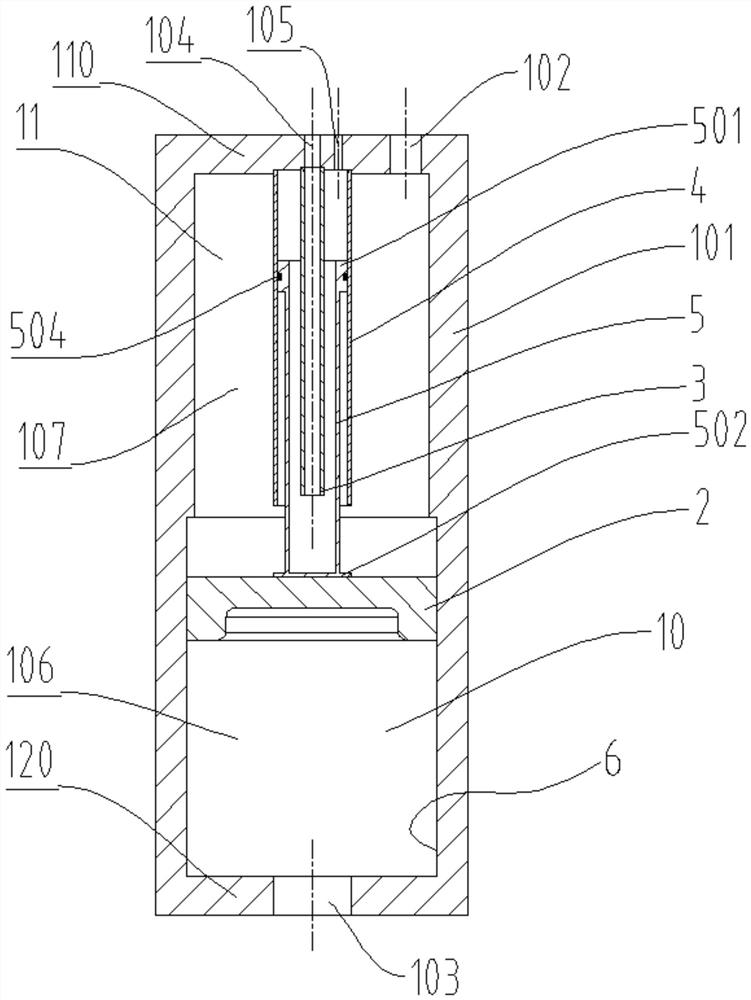
[0024] Such as figure 2 As shown, an accumulator utilizing waste heat from engine exhaust includes an accumulator body 1; the accumulator body 1 includes a cylinder 101, a piston assembly 2 and a cooling assembly;

[0025] The interior of the cylinder 101 has an axially extending stepped cavity 6, and an upper end cover 110 and a lower end cover 120 are respectively fixedly connected to the two ends of the stepped cavity 6; The lower large-diameter section 10 is formed, and the inner wall of the stepped chamber 6 is smooth.

[0026] The piston assembly 2 is a disc-shaped assembly whose size matches the size of the large-diameter section 10, and is assembled in the large-diameter section 10 in a sliding and sealing manner, and the piston assembly 2 can slide along the axial direction of the stepped chamber 6; The stroke of the piston assembly 2 is limited by the lower end...


PUM


Abstract

The invention provides an energy accumulator and energy-saving system utilizing waste heat of engine tail gas. A stepped cavity is arranged inside a cylinder barrel, and upper and lower end covers arefixedly connected to both ends of the cylinder barrel; the stepped cavity is composed of a small diameter section and a large diameter section; a piston assembly is assembled in the large diameter section, and divides the stepped cavity into a gas storage cavity and an oil storage cavity; a heat dissipation assembly is composed of a second pipeline, a third pipeline and a first pipeline with theinner diameters reduced in sequence and coaxially arranged from outside to inside in sequence, and the upper ends of the second pipeline and the first pipeline are both fixedly connected with the upper end cover; the lower end of the third pipeline is fixedly connected to the upper end of the piston assembly through a fixing plate, and a sealing ring sleeves the outer side of the upper end of thethird pipeline; an oil port is formed in the lower end cover; an air inlet is formed in the portion, corresponding to the first pipeline, of the upper end cover, an exhaust port is formed in the portion between the corresponding second pipeline and the first pipeline, and an air inflation port is formed in the portion corresponding to the periphery of the second pipeline. An energy accumulator body is connected with an exhaust pipeline through a reversing valve and a one-way valve. The energy accumulator can improve the working efficiency, and the system has good energy-saving and environmental protection effects.

Description

technical field [0001] The invention belongs to the technical field of hydraulic energy storage, and in particular relates to an energy accumulator and an energy-saving system utilizing waste heat from engine exhaust. Background technique [0002] An accumulator is an energy storage device in a hydraulic system. The accumulator converts the energy in the system into pressure energy or potential energy at an appropriate time and stores it; when the system needs it, the accumulator can convert the pressure energy or potential energy into hydraulic energy and release it to replenish the supply system. Accumulators can be divided into gravity type, spring type and gas-filled type according to the specific energy utilization form. Among them, the gas-filled accumulator is the most commonly used one. [0003] figure 1 A schematic diagram of the working process of a conventional air-filled accumulator is given. Assume that the accumulator works at figure 1 Point 1 in . The ac...

Claims


Application Information

Patent Timeline
Patent Type & Authority Applications(China)
IPC IPC(8): F02G5/02F15B1/04
CPCF02G5/02F15B1/04Y02T10/12
Inventor 李建松何伟平黎少辉许大华周波张文婷
Owner XUZHOU COLLEGE OF INDAL TECH
Why Eureka
Try Eureka