Battery hybrid heat exchange device and battery pack

A heat exchange device and battery technology, which is applied to secondary batteries, circuits, electrical components, etc., to achieve the effects of improving temperature consistency, simple structure, and uniform battery temperature

Pending Publication Date: 2022-06-10
ZHIJI AUTOMOTIVE TECH CO LTD
View PDF24 Cites 0 Cited by
  • Summary
  • Abstract
  • Description
  • Claims
  • Application Information

AI Technical Summary

Problems solved by technology

[0009] Aiming at the problem of low efficiency of single refrigeration and mixed refrigeration methods existing in the prior art, the present invention provides a battery hybrid heat exchange device and battery pack

Method used


Image

  • Battery hybrid heat exchange device and battery pack
  • Battery hybrid heat exchange device and battery pack
  • Battery hybrid heat exchange device and battery pack

Examples


Embodiment 1

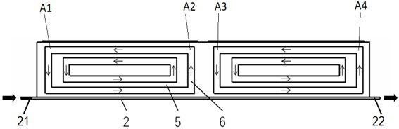
[0048] Continue to refer to image 3 , the reason why the refrigerant 6 will flow in this way, in addition to the heat absorption and heat release of the refrigerant 6 itself, another important reason is that along the direction of the metal plate 5, the liquid cooling circuit 2 forms a Temperature difference. like image 3 As shown, the heat conducting plate 1 has four positions A1, A2, A3, and A4 along the length direction of the liquid cooling circuit 2, and the corresponding temperatures are T1, T2, T3, and T4 respectively. Since the liquid cooling circuit 2 is always exchanging heat with the heat conduction plate 1, under the heating condition, the temperatures of the four positions A1, A2, A3, and A4 from high to low are T1>T2>T3>T4 respectively. Due to the temperature difference, in the closed circuit, the refrigerant 6 releases heat at the position A2 and absorbs heat at the position A1. Similarly, refrigerant 6 releases heat at position A4 and absorbs heat at posit...

Embodiment 2

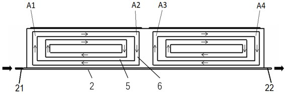
[0059] At the same time, a part of the honeycomb closed circuit of the heat conduction plate 1 away from the inlet 21 of the liquid cooling circuit 2, that is, a part of the refrigerant 6 in the metal plate 5 is at a position far away from the inlet 21 of the liquid cooling circuit 2, and this part of the refrigerant 6 flows to the battery module 3 Release heat, convert from gaseous state to liquid state and fall down the closed circuit (pipeline), such as Figure 5 indicated by the down arrow.

[0060] Similar to Embodiment 1, in this embodiment, the refrigerant 6 forms a flow in the honeycomb closed circuit, and during the flow process, the refrigerant 6 simultaneously transforms between liquid and gas. During the cyclic heat absorption and heat dissipation process of vaporization and liquefaction, the refrigerant 6 quickly releases the heat of the battery module 3 to the liquid cooling circuit 2, thereby ensuring efficient heat dissipation of the power battery and a stable ...


PUM

PropertyMeasurementUnit
phase transition temperatureaaaaaaaaaa
phase transition enthalpyaaaaaaaaaa

Abstract

The battery hybrid heat exchange device comprises a liquid cooling loop which is tightly attached to the bottom surface of a battery module; the heat conducting plate is tightly attached to the surface of the battery module, and at least one side surface of the heat conducting plate is in contact with the liquid cooling loop and exchanges heat with the liquid cooling loop; the heat conducting plate comprises a metal plate, the metal plate forms a closed loop on the heat conducting plate, and a refrigerant is arranged in the closed loop formed by the metal plate; wherein the heat conduction plate exchanges heat with the liquid cooling loop, so that refrigerants in the heat conduction plate are mutually converted and absorb and release heat in a gas state and a liquid state, and the heat conduction plate absorbs the heat of the battery module or transfers the released heat to the battery module. Through a mixed heat management technology combining a refrigerant direct cooling technology and a liquid cooling technology, the advantages of direct cooling phase change heat efficiency, uniform battery temperature, simple structure, relatively low cost and the like are realized, and the heat exchange efficiency of the battery module and a liquid cooling loop can be ensured, so that the temperature consistency of the battery pack is improved.

Description

technical field [0001] The invention relates to a battery cooling device and a corresponding battery, more specifically, to a battery hybrid heat exchange device and a battery pack. Background technique [0002] At present, there are four common cooling methods for power batteries: natural cooling, forced air cooling, liquid cooling, and direct refrigerant cooling. However, as users' requirements for electric vehicles increase, OEMs have higher and higher requirements for power performance and fast charging performance of power battery systems. Therefore, two efficient cooling methods, liquid cooling and refrigerant direct cooling, have become mainstream. At present, liquid cooling technology is the main cooling method for new energy vehicles due to its mature technology, low cost and simple structure. About 1 / 3 of that. However, the refrigerant direct cooling technology can only complete the heat dissipation function, resulting in the need to add additional heating equipm...

Claims


Application Information

Patent Timeline
Patent Type & Authority Applications(China)
IPC IPC(8): H01M10/613H01M10/6554H01M10/6568H01M10/6569
CPCH01M10/613H01M10/6568H01M10/6554H01M10/6569
Inventor 姜立彭荣华周东峰王洋东刘伟毕孟云
Owner ZHIJI AUTOMOTIVE TECH CO LTD
Why Eureka
Try Eureka