Heating device for food processing

A heating device and food processing technology, which can be used in household heating, heating methods, household heating, etc., can solve the problems of wasting thermal energy, speeding up equipment aging, and scaling affecting heat conduction efficiency, reducing energy consumption and maintaining heat exchange. Efficiency, avoid premature aging damage

Pending Publication Date: 2020-04-21
方绪龙
View PDF0 Cites 0 Cited by
  • Summary
  • Abstract
  • Description
  • Claims
  • Application Information

AI Technical Summary

Problems solved by technology

[0002] At present, most common food cooking equipment heats water through a fire-tube gas appliance or an electric heater that runs through the container. The heating equipment with this structure generally has problems such as large heat loss, especially after a period of use. The thermal efficiency drops seriously. The specific performance for:
[0003] The fire tube of the gas appliance or the electric heating rod of the electric heater, and the water storage container will accumulate a large amount of scale, resulting in serious heat loss, greatly reduced thermal efficiency, and significantly increased heating time; for example, the heat exchange capacity of the fire tube of the gas appliance is affected by the scale on the tube wall. The impact is reduced, a large amount of high-temperature flue gas is directly discharged through the fire tube, and the heat loss is serious. The scale on the surface of the electric heating rod of the electric heater not only makes it difficult to spread the heat outward (commonly known as dry burning), but also causes damage to t

Method used


Image

  • Heating device for food processing
  • Heating device for food processing
  • Heating device for food processing

Examples


Embodiment 1

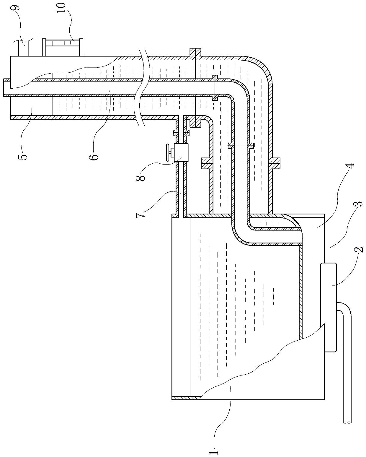
[0031] from figure 1 It can be seen that the technical solution of the present invention includes a burner, a main water tank 1 , a preheating water tank 5 , a water supply pipe 7 , and at least one smoke exhaust pipe 6 .

[0032] The top of the main water tank 1 is open, the bottom of the main water tank 1 is a combustion part, and the burner burner 2 is arranged on the combustion part 3; Body, the side wall of the main water tank 1 and the pipe wall junction of the smoke exhaust pipe 6 are fixedly connected by welding; The combustion part 3 is connected, and the rear pipe body of the smoke exhaust pipe located outside the main water tank is assembled into an L shape by a multi-section pipe body through a flange or bayonet detachable connection and extends upward;

[0033] The preheating water tank 5 also adopts a split structure of multi-section boxes, and the boxes of each section are detachably connected into one body through flanges or bayonet joints, and are set in the ...

Embodiment 2

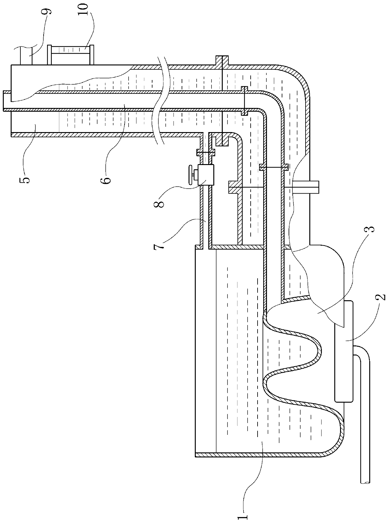
[0040] from figure 2 It can be seen that the difference between this embodiment and Embodiment 1 is that the bottom plate of the main water tank 1 is in a concave shape, which increases the heated area at the bottom of the main water tank, so that the lower part of the main water tank 1 naturally forms a combustion area (i.e. combustion part), in order to achieve the purpose of collecting smoke and avoiding heat loss. In this embodiment, the bottom plate of the main water tank 1 is designed as a plate with a wavy cross-section, which further increases the heated area of ​​the bottom of the tank.

[0041] Other features of this embodiment are the same as Embodiment 1.

Embodiment 3

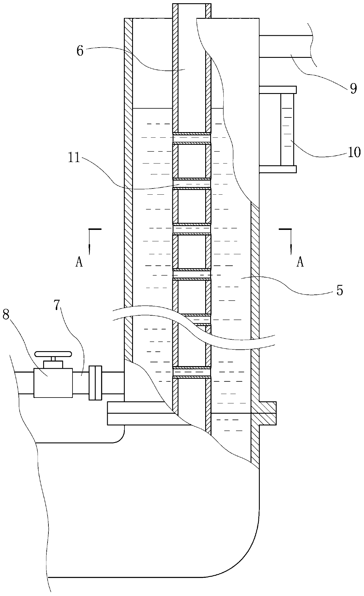
[0043] from Figure 3 ~ Figure 4 It can be seen that the difference between this embodiment and Embodiment 1 is that the outer section of the smoke exhaust pipe 6 is provided with a plurality of water pipes 11 that run through the smoke exhaust pipe transversely, and the two ports of the water pipe 11 are connected with the smoke exhaust pipe 6. The pipe wall is welded and connected so that the two ends of the water pipe are communicated with the preheating water tank 5 to increase the fluidity of the water in the tank and make full use of the waste heat of the exhaust pipe exhaust gas to heat up the spare water in the preheating water tank.

[0044] Another difference between this embodiment and Embodiment 1 is that a fan is installed at the end of the exhaust pipe 6 as a forced air exhaust device, so as to enhance the gas flow of the exhaust pipe and the combustion part and prevent the fuel from burning. full.

[0045] In addition, according to the use of the heating device, ...


PUM


Abstract

The invention relates to the technical field of food processing equipment, in particular to a heating device for food processing. At present, food cooking equipment generally has the problems of low heat efficiency and the like. According to the technical scheme, the device comprises a main water tank, a preheating water tank, a water supplementing pipe and at least one smoke exhaust pipe, whereinthe preheating water tank and the smoke exhaust pipe are designed in a split mode; the lower end of the smoke exhaust pipe penetrates the side wall of the main water tank and is communicated with a combustion part at the bottom of the main water tank; the preheating water tank is assembled with a smoke exhaust pipe outside the main water tank in a sleeving manner and is fixedly connected with theside part of the main water tank to form a barrel-shaped water jacket surrounding the smoke exhaust pipe; and the preheating water tank is communicated with the main water tank through the water supplementing pipe. The main water tank can be used for cooking food and can also be used as a steam generator to be matched with a steam box for use. Water supplementation has no influence on the cookingeffect in the processing process of the device, the utilization rate of heat energy is greatly increased, accumulated scale is conveniently removed, and the device is suitable for large-scale and continuous operation of food processing enterprises or restaurants and the like.

Description

technical field [0001] The invention relates to the technical field of food processing equipment, in particular to a heating device for food processing. Background technique [0002] At present, most common food cooking equipment heats water through a fire-tube gas appliance or an electric heater that runs through the container. The heating equipment with this structure generally has problems such as large heat loss, especially after a period of use. The thermal efficiency drops seriously. The specific performance for: [0003] The fire tube of the gas appliance or the electric heating rod of the electric heater, and the water storage container will accumulate a large amount of scale, resulting in serious heat loss, greatly reduced thermal efficiency, and significantly increased heating time; for example, the heat exchange capacity of the fire tube of the gas appliance is affected by the scale on the tube wall. The impact is reduced, a large amount of high-temperature flue ...

Claims


Application Information

Patent Timeline
IPC IPC(8): A47J27/14A47J27/16A47J36/00F24C15/20
CPCA47J27/14A47J27/16A47J36/00F24C15/20
Inventor 方绪龙
Owner 方绪龙
Why Eureka
Try Eureka