Plate cooler and using method thereof

A technology of plate cooler and protection plate, applied in the direction of heat exchanger type, heat exchanger shell, indirect heat exchanger, etc. Maintain heat exchange efficiency and the effect of thermal energy, high strength, and wind resistance unchanged

Active Publication Date: 2017-10-20
江苏鑫昊空调设备有限公司
View PDF5 Cites 2 Cited by
  • Summary
  • Abstract
  • Description
  • Claims
  • Application Information

AI Technical Summary

Problems solved by technology

[0005] However, the existing equipment has the following deficiencies. First, it cannot freely switch between the streamline guide trough and the equipotential line pressure equalizing trough. Should priority be given to increasing the energy recovery rate, lengthening the streamline guide trough, or giving priority to keeping the wind resistance constant? The number of pressure equalizing grooves along the equipotential line has become a design bottleneck, and the overall adaptability of the equipment is poor. Second, during the use of the plate cooler, due to improper operation of the water treatment equipment, the water quality control is not up to standard, and the unqualified softened water Injected into the heating system, the calcium, magnesium and carbonate in the water are decomposed into calcium carbonate and calcium hydroxide after being heated
Due to the poor thermal conductivity of scale, the heat exchange efficiency of the heat exchanger is reduced and the heat energy is seriously wasted, which affects the heating effect and has a serious negative impact on the heating unit.

Method used


Image

  • Plate cooler and using method thereof
  • Plate cooler and using method thereof
  • Plate cooler and using method thereof

Examples


Embodiment 1

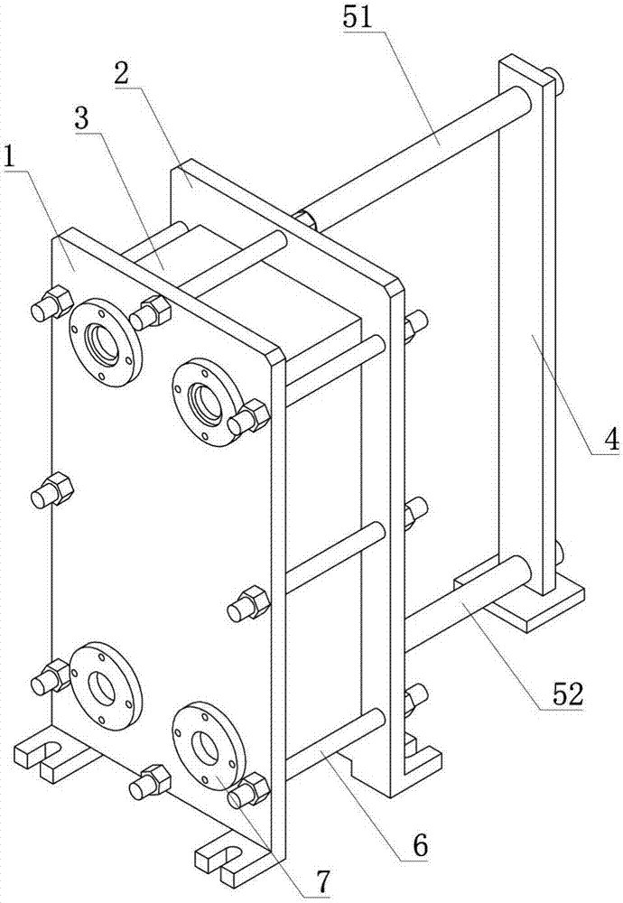
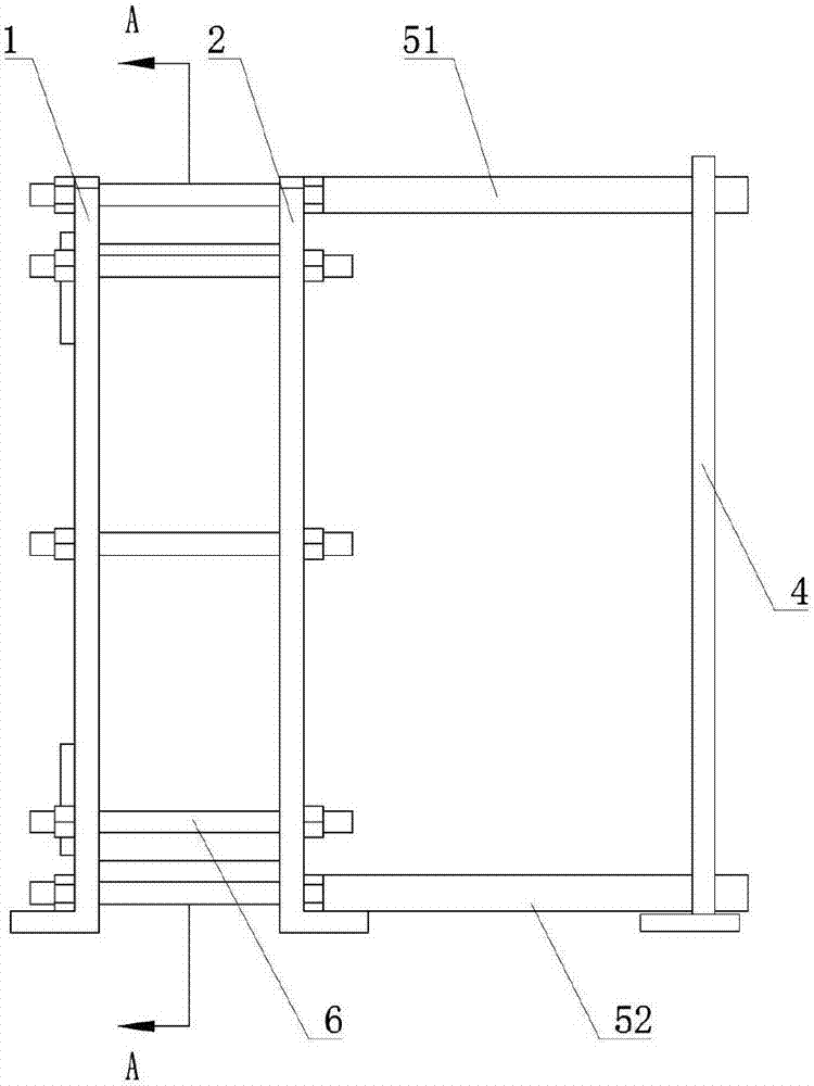
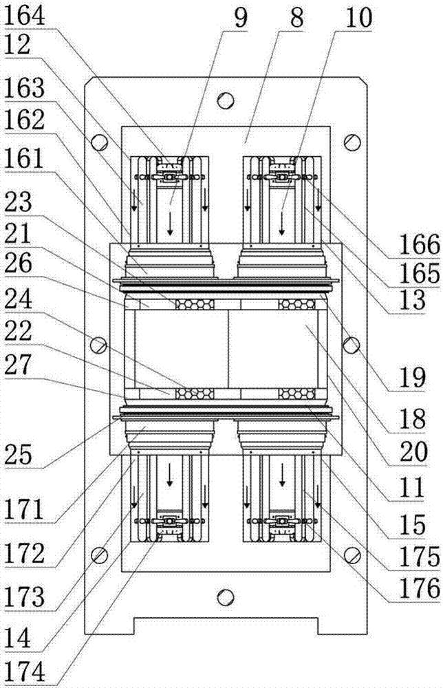
[0047] Such as figure 1 , figure 2 , image 3 As shown, the plate cooler includes a front fixed frame plate 1, a rear fixed frame plate 2, a protection plate 3, a heat exchange plate group, a supporting foot 4, an upper guide rod 51, a lower guide rod 52, tension bolts 6, monitoring The hole cover 7, the front fixed frame plate 1 is installed in front of the protective plate 3, the rear fixed frame plate 2 is installed behind the protective plate 3, the heat exchange plate group is built in the protective plate 3, the upper guide rod 51 runs through the protective plate 3, and the rear end extends out The rear fixed frame plate 2 is connected to the upper end of the support foot 4, the lower guide rod 52 runs through the protection plate 3, and the rear end extends out. The rear fixed frame plate 2 is connected to the lower end of the support foot 4, and the upper guide rod 51 is symmetrical to the lower guide rod 52 Parallel arrangement; the middle area of ​​the front fixe...

Embodiment 2

[0059] Such as figure 1 , figure 2 , image 3 As shown, the plate cooler includes a front fixed frame plate 1, a rear fixed frame plate 2, a protection plate 3, a heat exchange plate group, a supporting foot 4, an upper guide rod 51, a lower guide rod 52, tension bolts 6, monitoring The hole cover 7, the front fixed frame plate 1 is installed in front of the protective plate 3, the rear fixed frame plate 2 is installed behind the protective plate 3, the heat exchange plate group is built in the protective plate 3, the upper guide rod 51 runs through the protective plate 3, and the rear end extends out The rear fixed frame plate 2 is connected to the upper end of the support foot 4, the lower guide rod 52 runs through the protection plate 3, and the rear end extends out. The rear fixed frame plate 2 is connected to the lower end of the support foot 4, and the upper guide rod 51 is symmetrical to the lower guide rod 52 Parallel arrangement; the middle area of ​​the front fixe...


PUM


Abstract

The invention discloses a plate cooler, and relates to the heat exchange technology. The plate cooler is used for solving the problems that existing equipment cannot be freely switched between a flow line guide groove and suitable equipotential line pressure sharing grooves priority is given to energy recovery increase, the flow line guide groove is lengthened, priority is given to unchanged air resistance keeping, the number of the suitable equipotential line pressure sharing grooves is increased, a design bottleneck exists, and the equipment overall adaptation condition is poor. The plate cooler comprises a front fixed frame plate, a back fixed frame plate, a protection plate, a heat exchange plate set, a supporting ground foot, an upper guide rod, a lower guide rod, a tensioning bolt and a monitoring hole cover; and the heat exchange plate set comprises a heat exchange sheet, a hot fluid pipe, a cold fluid pipe and a flow guide structure. In an energy recovery occasion for increasing the energy recovery rate or increasing the air amount, the air resistance can be kept unchanged, and switching between two states is achieved. The invention further provides a using method of the plate cooler.

Description

technical field [0001] The present invention relates to heat exchange technology, in particular, to a plate cooler and a method of use thereof. Background technique [0002] The plate cooler is a new type of high-efficiency heat exchanger that is stacked by a series of metal sheets with a certain corrugated shape. Thin rectangular channels are formed between the various plates, and heat exchange is performed through the half plates. Compared with conventional shell-and-tube heat exchangers, its heat transfer coefficient is much higher under the same flow resistance and pump power consumption, and it tends to replace shell-and-tube heat exchangers within the applicable range. There are two main types of plate heat exchangers: frame type (detachable type) and brazed type. The plate forms are mainly herringbone corrugated plate, horizontal flat corrugated plate and tumor-shaped plate. [0003] The heat transfer plates are cold stamped to form different corrugated shapes. Ther...

Claims


Application Information

Patent Timeline
Patent Type & Authority Applications(China)
IPC IPC(8): F28D9/00F28F9/22F28G9/00
Inventor 刘有萍杨焱
Owner 江苏鑫昊空调设备有限公司
Why Eureka
Try Eureka