Underground water level detection device for hydrogeological exploration
A groundwater level and detection device technology, applied in measuring devices, water resource assessment, buoy liquid level indicators, etc., can solve problems such as well wall collapse, well wall support tube, failure of well wall support, and detectors that cannot follow real-time adjustments, etc. , to achieve the effect of high universality, simple and stable structure
- Summary
- Abstract
- Description
- Claims
- Application Information
AI Technical Summary
Problems solved by technology
Method used
Image
Examples
Embodiment 1
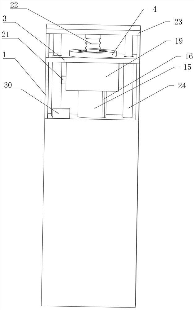
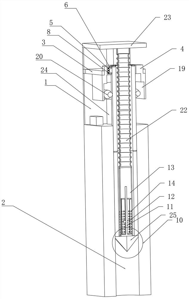
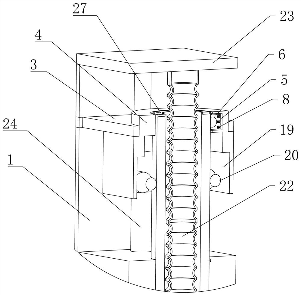
[0026] Embodiment 1, the present invention is a groundwater level detection device for hydrogeological exploration, comprising a support base 1 placed on the ground, and a pre-drilled measuring hole 2 on the ground. The detector goes deep into the measuring hole 2, and measures the water level in the measuring hole 2. The upper end of the supporting base 1 is fixedly connected with a fixed horizontal plate 3, and the fixed horizontal plate 3 provides the follow-up structure. The fixed support foundation, the middle position of the fixed horizontal plate 3 is fixedly connected with a limit ring sleeve 4, and the limit ring sleeve 4 is fixedly connected with a number of sliding boxes 5, and the sliding boxes 5 are all along the The limit ring sleeve 4 is radially slidably connected with a sliding limit sleeve 6, and the sliding limit sleeve 6 is rotatably connected with a limit ball 7, and the limit ball 7 is in the sliding limit sleeve 6. Free rotation inside, the sliding limit...
Embodiment 2
[0027] Embodiment 2, on the basis of Embodiment 1, in the process of supporting the inner wall of the measuring hole 2 through the measuring cylinder 9, during the disassembling process of the measuring cylinder 9, due to the influence of the geological environment, It may cause damage to the upper end of the measurement hole 2, especially the upper port, or even collapse. Therefore, this embodiment provides a combined measurement cylinder 9 to avoid damage to the inner wall of the measurement hole 2. Specifically, the measuring cylinder 9 includes two half-arc cylinders 15 and two limit arc plates 16 . Both sides of the two half-arc cylinders 15 are provided with arc-shaped limit rails 17 . The arc-shaped limiting bars 18 are fixedly connected to the arc-shaped limiting rails 17. The half-arc cylinder 15 and the limiting arc-plate 16 are closed to form a cylinder. The cooperation of the half arc cylinder 15 and the limit arc plate 16 realizes the combination of the measuring ...
Embodiment 3
[0028] Embodiment 3, on the basis of Embodiment 1, when the holding force of the spring 8 and the limiting ball 7 on the measuring cylinder 9 is too large, it is difficult to realize the measurement cylinder 9 through external pulling. The retraction and release of 9 is time-consuming and laborious. When the holding force is too small, it cannot achieve a good fixing effect in the up and down direction. Therefore, this embodiment provides a method for measuring the measuring cylinder 9 under the action of a large holding force. The structure for retracting and placing, specifically, the lower end of the limit ring sleeve 4 is fixedly connected with a fixed sleeve 19, and the front and rear sides of the fixed sleeve 19 are rotatably connected with conveying rollers 20. The idler 20 is in the shape of a dumbbell, and the middle arc surface of the conveying idler 20 is in contact with the outer wall of the measuring cylinder 9. Through the reverse rotation of the two conveying idl...
PUM
 Abstract
Description
Claims
Application Information
 - R&D
- Intellectual Property
- Life Sciences
- Materials
- Tech Scout
- Unparalleled Data Quality
- Higher Quality Content
- 60% Fewer Hallucinations
Browse by: Latest US Patents, China's latest patents, Technical Efficacy Thesaurus, Application Domain, Technology Topic, Popular Technical Reports.
© 2025 PatSnap. All rights reserved.Legal|Privacy policy|Modern Slavery Act Transparency Statement|Sitemap|About US| Contact US: help@patsnap.com


