Distributed novel direct current testing device

A DC test, decentralized technology, applied in the direction of fault location, electrical components, electromagnetic wave transmission system, etc., can solve the problems of bulky and bulky test devices, inconvenient portability of test devices, and device application of signals, etc., to achieve fast and convenient implementation, easy implementation, The effect of light implementation

Pending Publication Date: 2022-06-03
CHINA SOUTHERN POWER GRID COMPANY +1
View PDF0 Cites 0 Cited by
  • Summary
  • Abstract
  • Description
  • Claims
  • Application Information

AI Technical Summary

Problems solved by technology

In this test mode, conventional AC sampling signals, conventional switching signals, optical fiber FT3 signals, and optical fiber Ethernet signals are applied at different locations far away. Even if a single test device can output DC control and protection devices, various types of data are required. , it is obviously impossible to apply signals to devices in different positions at the same time, so multiple test devices are required to cooperate to complete
[0004] In order to meet the test requirements of various control and protection devices of the DC system, the test device needs to integrate various modules such as high-power power amplifier module, input and output module, optical fiber FT3 module, optical fiber Ethernet module, management module, etc., according to the conventional design. Test devices are often bulky and bulky, and multiple test devices are not easy to carry, and the cooperation between multiple devices requires a complex test environment

Method used


Image

  • Distributed novel direct current testing device
  • Distributed novel direct current testing device

Examples


Embodiment Construction

[0014] The present invention will be further described below in conjunction with the accompanying drawings. The following examples are only used to illustrate the technical solutions of the present invention more clearly, and cannot be used to limit the protection scope of the present invention.

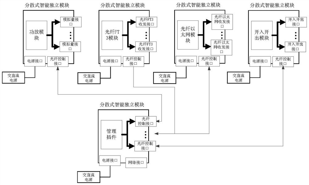
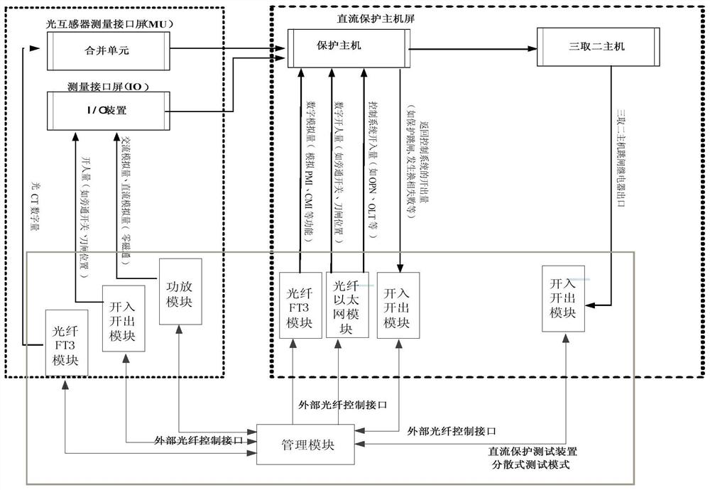
[0015] like figure 1 As shown in the figure, a new type of distributed DC test device includes a management module, a number of power amplifier modules, a number of input and output modules, a number of optical fiber Ethernet modules and a number of optical fiber FT3 modules; all modules are scattered and arranged, and each module is an independent device , in which generally one management module is set, and the number of other modules depends on the number of devices under test.

[0016] The power amplifier module, I / O module, optical fiber Ethernet module and optical fiber FT3 module are respectively arranged near the corresponding device under test, and are respectively connecte...


PUM


Abstract

The invention discloses a distributed novel direct current testing device which adopts distributed distribution, all functional modules are distributed near a tested device, centralized management is performed through a management module, testing of a direct current system can be completed without a plurality of testing devices, implementation is rapid and convenient, and a complex testing environment does not need to be set up. Meanwhile, the optical fiber interface is adopted, the situation that on-site standby optical fibers of a direct-current system are sufficient can be fully utilized, the modules are convenient to arrange in a distributed mode, the method is more suitable for the characteristics of on-site device cross-floor and cross-interval arrangement, and the method is lighter and easier to implement.

Description

technical field [0001] The invention relates to a distributed new type of direct current test device, which belongs to the technical field of ultra-high voltage direct current test. Background technique [0002] In recent years, more and more DC transmission projects have been put into operation, and the reliable operation of the DC protection system has become more and more important for ensuring the safe and stable operation of the DC power grid. [0003] Due to the complexity of the DC system, various protection devices are physically distributed according to the system, and the interconnection between systems is mostly interconnected by optical fibers. During the on-site acceptance, the entire system often needs to be checked. In this test mode, conventional AC sampling signals, conventional switching signals, optical fiber FT3 signals, and optical fiber Ethernet signals are applied at different locations far away. Even if a single test device can output DC control and p...

Claims


Application Information

Patent Timeline
Patent Type & Authority Applications(China)
IPC IPC(8): G01R31/08H04B10/075
CPCG01R31/08H04B10/075Y04S40/124
Inventor 李捷丁晓兵孔飞黄河田得良张弛田庆刘鹏李兴建张建锋笃峻于哲
Owner CHINA SOUTHERN POWER GRID COMPANY
Why Eureka
Try Eureka