Cutting device for hand bone butt joint operation
A cutting device and technology for surgery, applied in the medical field, can solve problems such as unfavorable use, inability to position and engage fingers, long and crooked fingers, etc., and achieve smooth cutting effect, fast cutting operation, and increased stability.
- Summary
- Abstract
- Description
- Claims
- Application Information
AI Technical Summary
Problems solved by technology
Method used
Image
Examples
Embodiment 1
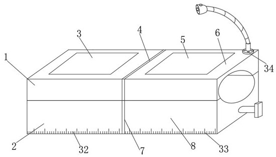
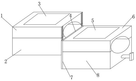
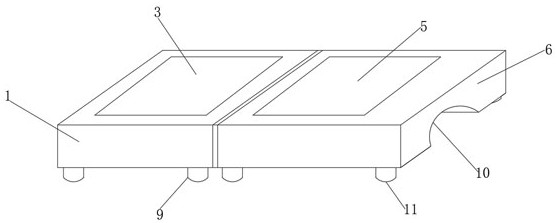
[0027] like Figure 1-7 As shown in the figure, a cutting device for hand-bone butt joint operation includes No. 1 metal frame 1, No. 2 metal frame 2, No. 3 metal frame 6 and No. 4 metal frame 8, and one between No. 1 metal frame 1 and No. 2 metal frame 2 For combination, the No. 3 metal frame 6 and the No. 4 metal frame 8 are combined. The inner sides of the No. 1 metal frame 1 and the No. 2 metal frame 2 are respectively provided with an upper slide 19 and a lower slide 22, and the No. 3 metal frame 6 and The inner side of the fourth metal frame 8 is respectively installed with the upper sliding rail 4 and the lower sliding rail 7 , the inner end of the fourth metal frame 8 is provided with a cutting groove 14 , and an annular knife seat 15 is arranged inside the cutting groove 14 .
[0028]Further, a No. 1 positioning support plate 3 is installed in the inner position of the No. 1 metal frame 1, a No. 2 positioning support plate 5 is installed in the inner position of the N...
Embodiment 2
[0032] On the basis of Example 1, as Figure 1-7 As shown in the figure, a cutting device for hand-bone butt joint operation includes No. 1 metal frame 1, No. 2 metal frame 2, No. 3 metal frame 6 and No. 4 metal frame 8, and one between No. 1 metal frame 1 and No. 2 metal frame 2 For combination, the No. 3 metal frame 6 and the No. 4 metal frame 8 are combined. The inner sides of the No. 1 metal frame 1 and the No. 2 metal frame 2 are respectively provided with an upper slide 19 and a lower slide 22, and the No. 3 metal frame 6 and The inner side of the fourth metal frame 8 is respectively installed with the upper sliding rail 4 and the lower sliding rail 7 , the inner end of the fourth metal frame 8 is provided with a cutting groove 14 , and an annular knife seat 15 is arranged inside the cutting groove 14 .
[0033] Further, a drive connection port 26 is opened at the inner position of the annular knife seat 15, the drive connection port 26 is connected with the rotating sha...
Embodiment 3
[0036] On the basis of Embodiment 1 and Embodiment 2, as Figure 1-8 As shown in the figure, a cutting device for hand-bone butt joint operation includes No. 1 metal frame 1, No. 2 metal frame 2, No. 3 metal frame 6 and No. 4 metal frame 8, and one between No. 1 metal frame 1 and No. 2 metal frame 2 For combination, the No. 3 metal frame 6 and the No. 4 metal frame 8 are combined. The inner sides of the No. 1 metal frame 1 and the No. 2 metal frame 2 are respectively provided with an upper slide 19 and a lower slide 22, and the No. 3 metal frame 6 and The inner side of the fourth metal frame 8 is respectively installed with the upper sliding rail 4 and the lower sliding rail 7 , the inner end of the fourth metal frame 8 is provided with a cutting groove 14 , and an annular knife seat 15 is arranged inside the cutting groove 14 .
[0037] Further, a positioning support 27 is installed at the bottom position of the No. 1 positioning support plate 3, a No. 2 positioning support 2...
PUM
 Abstract
Description
Claims
Application Information
 - R&D
- Intellectual Property
- Life Sciences
- Materials
- Tech Scout
- Unparalleled Data Quality
- Higher Quality Content
- 60% Fewer Hallucinations
Browse by: Latest US Patents, China's latest patents, Technical Efficacy Thesaurus, Application Domain, Technology Topic, Popular Technical Reports.
© 2025 PatSnap. All rights reserved.Legal|Privacy policy|Modern Slavery Act Transparency Statement|Sitemap|About US| Contact US: help@patsnap.com


