Engineering surveying pay-off device

A wire pay-off device and engineering measurement technology, applied in the direction of manufacturing tools, cleaning methods for using tools, cleaning methods and utensils, etc., can solve problems such as damage to the service life of the ink fountain, affecting the use of the ink fountain, damage and breakage of cotton threads, etc., to improve continuous use. Duration, guaranteed service life, and guaranteed ink volume

Inactive Publication Date: 2022-06-07
李万明
View PDF0 Cites 1 Cited by
  • Summary
  • Abstract
  • Description
  • Claims
  • Application Information

AI Technical Summary

Problems solved by technology

[0004] However, the current ink fountain mainly has the following problems in the use process: First, when the ink fountain is used, the cotton thread will often rub against the ground or the wall when it is pulled out. If things go on like this, the cotton thread will be damaged and broken, and the cotton thread needs to be replaced. The old cotton thread is taken out from the ink fountain in circles, and then the new cotton thread is wound on the ink fountain. This process is time-consuming and laborious, which affects the use of the ink fountain; Ink, the way of refilling the ink is often to manually pour the ink of a separate device into the ink fountain, which wastes time and affects the work progress; again, the ink fountain will collect the attachments on the cotton thread into the ink fountain when it takes up the thread, which is easy Damage to the parts inside the ink fountain will affect the service life of the ink fountain

Method used


Image

  • Engineering surveying pay-off device
  • Engineering surveying pay-off device
  • Engineering surveying pay-off device

Examples


Embodiment Construction

[0035] Embodiments of the present invention will be described below with reference to the accompanying drawings. During this process, in order to ensure the clarity and convenience of the description, we may exaggerate the width of the lines or the size of the components in the illustrations.

[0036] In addition, the following terms are defined based on the functions in the present invention, and may be different depending on the user, the operator's intention, or convention. Therefore, these terms are defined based on the entire content of this specification.

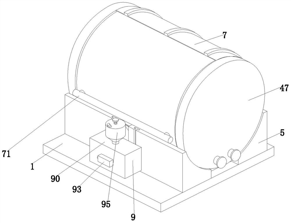
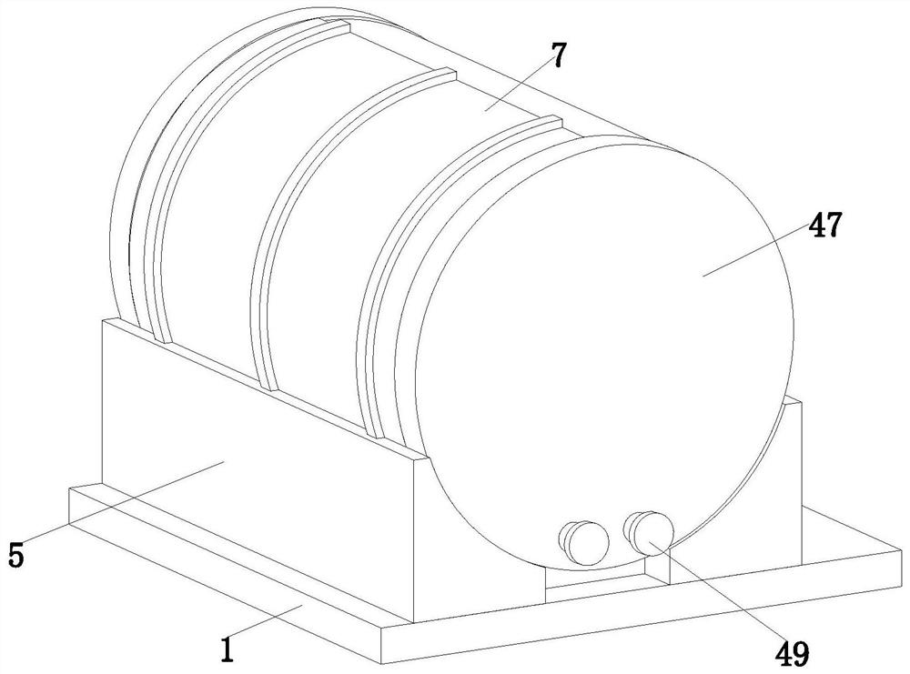
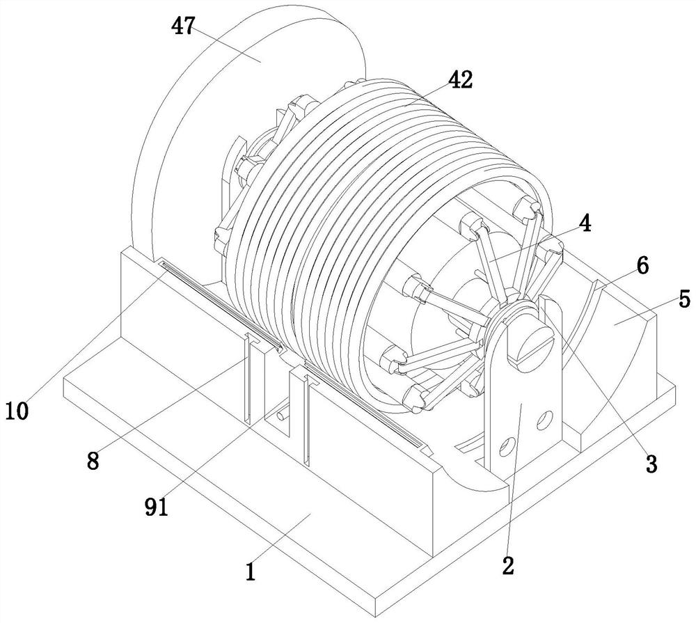
[0037] see figure 1 , figure 2 , image 3 and Figure 10 , an engineering measurement and pay-off device, comprising a base 1; the upper end surface of the base 1 is symmetrically installed with two support plates 2, and the upper ends of the two support plates 2 are provided with a U-shaped groove 3, and the U-shaped groove 3 is provided with A winding device 4 is provided, an arc-shaped block 5 is arranged bel...


PUM


Abstract

The invention relates to the technical field of engineering surveying, in particular to an engineering surveying pay-off device. Comprising a base, two supporting plates are installed on the upper end face of the base in a bilateral symmetry mode, U-shaped grooves are formed in the upper ends of the two supporting plates, winding devices are arranged on the U-shaped grooves, arc-shaped blocks are arranged below the winding devices, the arc-shaped blocks are installed on the upper end face of the base, and sliding grooves are evenly formed in the rear sides of the upper end faces of the arc-shaped blocks; an isolation cover is installed on the sliding groove in a sliding fit mode, a pull rod is arranged on the front side of the isolation cover, the pull rod is installed on the circumferential outer wall of the isolation cover, a clamping groove is formed in the end face of the front side of the arc-shaped block, an ink moistening device is installed on the clamping groove, a clamping opening is formed in the front side of the upper end face of the arc-shaped block, and an elastic piece is arranged in the clamping opening; the front side end part of the isolation cover is inserted into the bayonet and is fixed with the elastic sheet in an abutting manner; according to the invention, the ink fountain cotton thread is convenient to replace, the continuous use time of the ink fountain is prolonged, and the service life of the ink fountain is ensured.

Description

technical field [0001] The invention relates to the technical field of engineering measurement, in particular to an engineering measurement pay-off device. Background technique [0002] Engineering surveying refers to the general term of various measurement theories, methods and technologies used in the survey, design, construction and management stages of engineering construction. The laying-out operation of engineering surveying is to facilitate the work of workers and ensure that workers can strictly follow the drawings for construction. , Theodolite, steel tape measure, line sinker, ink fountain, etc. will be used in the process of laying out the line, among which the ink fountain is mainly used to eject the axis of the construction level. [0003] The ink fountain is composed of ink tank, reel, cotton thread, class mother and ink swab. When using, first fix one end of the cotton thread after moistening the ink, then pull out the cotton thread to straighten and tighten i...

Claims


Application Information

Patent Timeline
Patent Type & Authority Applications(China)
IPC IPC(8): B25H7/04B08B1/00B08B1/02B65H75/42B65H75/44
CPCB25H7/045B65H75/4492B65H75/4457B65H75/4439B65H75/44B65H75/42B08B1/002B08B1/02B65H2701/35
Inventor 李万明郭猛
Owner 李万明
Why Eureka
Try Eureka