
Automobile seat

A car seat and seat technology, which is applied to vehicle seats, movable seats, vehicle parts, etc., can solve the problems of increasing the height of the seat space, increasing the complexity of the structure, and the difficulty of processing, so as to save time for design , to ensure stability and anti-tipping performance, and to save material costs

Pending Publication Date: 2022-06-07
CHERY AUTOMOBILE CO LTD
View PDF18 Cites 0 Cited by
  • Summary
  • Abstract
  • Description
  • Claims
  • Application Information

AI Technical Summary

Problems solved by technology

The above scheme has the following problems: one is that the rotating mechanism is arranged between the slide rail 2 fixed on the vehicle floor and the seat cushion C, and it is undoubtedly necessary to completely redesign the connection structure between the sliding rail 2 and the rotating mechanism and the seat. The connection structure between the seat cushion C and the rotating mechanism obviously increases the complexity of the structure; the second is to increase the space height of the seat, which poses a new problem for the vehicle space; in the third rotating mechanism, the platform in the turntable 1 The bracket 1d is riveted on the upper platform 1c, the lower platform 1b is fixed on the base 1a by bolts, and the balls 1e, 1f are placed in the ring between the upper platform 1c and the platform bracket 1d and the lower platform 1b and the platform bracket 1d. The cross-section is at the arc-shaped groove area, so as to realize the rotating structure of the seat. This kind of non-standard structure bearing is not only difficult to process and high in cost, especially when the seat is loaded, the resultant force of the non-standard structure bearing and the shaft core of the bearing The probability of coincidence is almost zero. Once the parts of the upper platform 1c, platform bracket 1d and lower platform 1b that accommodate the balls 1e and 1f are deformed, the rotating mechanism will fail
[0003] In addition, there are also a variety of seat rotation structure schemes, such as "a rotatable car seat" (CN113733999 A), in which the rotating part is the rotating shaft 2, and the middle part of the bottom plate 1 top and the bottom of the rotating shaft 2 Fixed connection, the top of the rotating shaft 2 is fixedly connected with the middle part of the bottom of the fixed plate 3, and the fixed plate 3 is connected to the base 7. It can be seen that the seat rotates around the rotating shaft 2, and the seat shakes when the vehicle bumps or suddenly stops, accelerates or even collides A huge bending moment will be applied to the rotating shaft 2, and in severe cases, the rotating shaft 2 will be broken, which poses a serious safety hazard, and this scheme does not involve the sliding mechanism of the seat

Method used


Image

  • Automobile seat
  • Automobile seat
  • Automobile seat

Examples


Embodiment approach

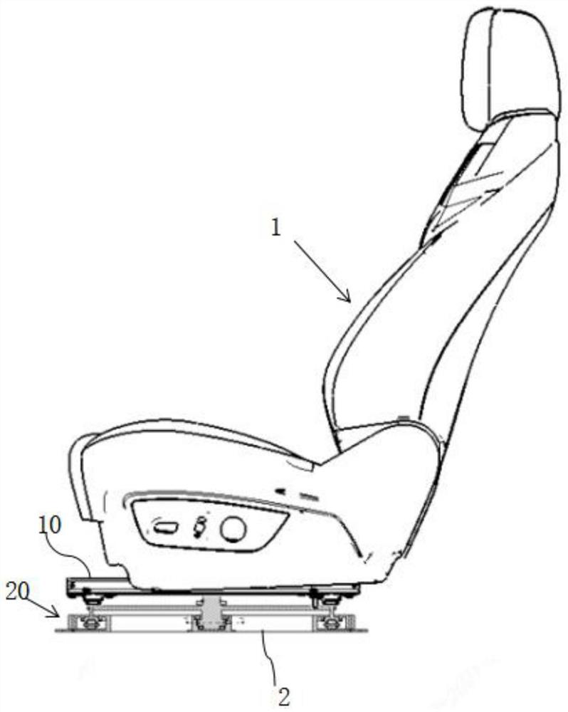
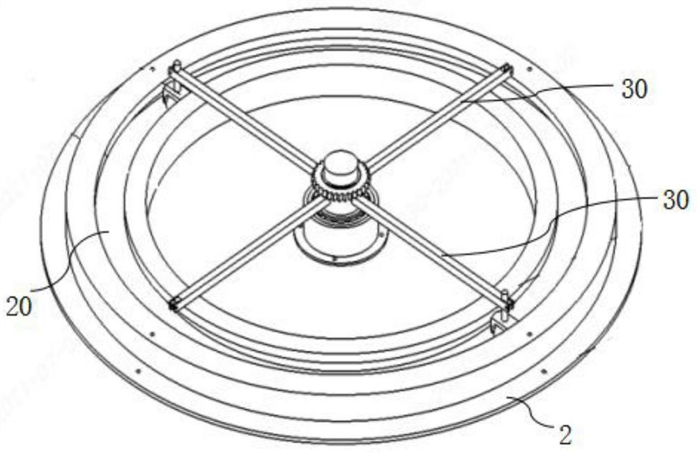
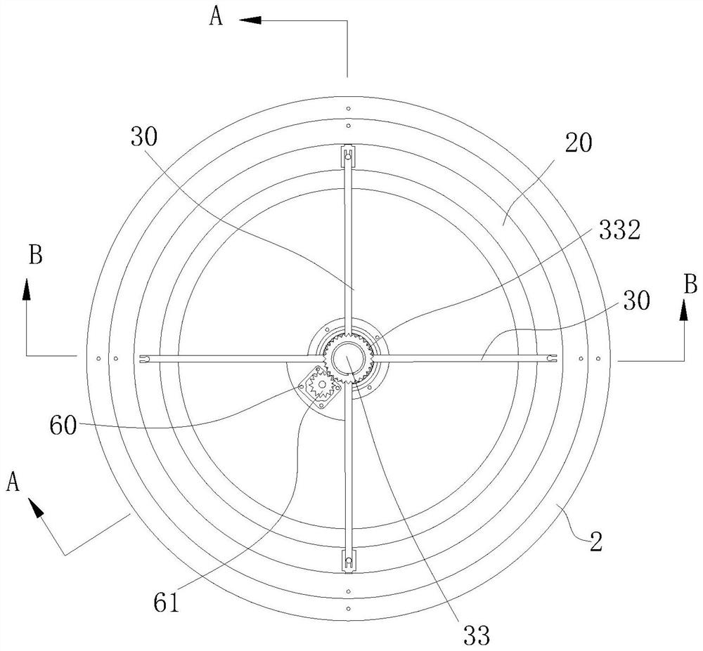
[0018] One is: the cross-section of the annular track 20 is a closed groove with the notch upward, and the roller 31 provided on the turret 30 is placed in the groove cavity of the annular track 20 and forms a rolling fit with the bottom of the groove, such as: Figures 1 to 5 shown.

[0019] The second is: the circumferential inner and outer side sections of the annular track 20 are in the shape of a concave arc, and the slotted slider 34 on the turret 30 is clamped downward on the annular track 20 . superior.

[0020] The matching structure between the annular track 20 and the groove-shaped slider 34 in the above-mentioned solution 2 can be a linear bearing structure scheme, which can reduce frictional noise and improve the stability of rotating operation, and the groove-shaped slider can be used. 34 is connected to the guide rail 11 in the sliding mechanism assembly 10 , and the grooved slider 34 is also connected to the turret 30 , which will help ensure the reliability a...


PUM


Abstract

The invention relates to an automobile seat, which is characterized in that the lower part of the seat is connected with a sliding mechanism assembly, two guide rails in the sliding mechanism assembly are arranged on an automobile floor in parallel at an interval, an annular rail is arranged on an automobile floor, at least three sliding blocks or rollers are symmetrically arranged on a rotating frame, and the sliding blocks or rollers are in rolling or sliding fit with the annular rail; a guide rail on the sliding mechanism assembly is fixedly connected to the rotating frame. The seat and the sliding mechanism assembly connected with the lower portion of the seat are maintained, namely an existing seat and an existing sliding mechanism assembly connected with the lower portion of the seat are maintained, a guide rail in the sliding mechanism assembly is connected to the rotating frame, and the rotating frame is matched with the annular rail to achieve rotation of the seat. A lower sliding mechanism commonly adopted by an existing vehicle seat does not need to be changed, only a rotating mechanism composed of the rotating frame and the annular rail needs to be provided, the sliding guide rail is installed on the rotating frame, design time and material cost are saved, and the stability and the anti-tipping performance of the seat are guaranteed through the rotating matching scheme of the rotating frame and the annular rail.

Description

technical field [0001] The present invention relates to vehicle seats, particularly seats with positional movement and rotation on vehicles. Background technique [0002] Traditional car seats generally can only be adjusted in the up and down, front and rear directions. In order to satisfy the seat orientation and seat adjustment of the driver and passenger, a patent document entitled "Rotating and Sliding Seat for Vehicles" (CN1938177A) discloses related technical solutions, including a turntable 1, a slide rail 2, and an upper rail of the slide rail 2 There is a base 1a on 2a, and a lower platform 1b on the fixed side is provided on the board surface of the base 1a; The above solution has the following problems: one is that the rotating mechanism is arranged between the sliding rail 2 fixed on the vehicle floor and the seat cushion C, it is undoubtedly necessary to completely redesign the connection structure and seat between the sliding rail 2 and the rotating mechanism....

Claims


Application Information

Patent Timeline
Patent Type & Authority Applications(China)
IPC IPC(8): B60N2/07B60N2/14
CPCB60N2/0722B60N2/14B60N2/146
Inventor 王亮平沈光勇刘富林刘正坤
Owner CHERY AUTOMOBILE CO LTD
Learn More