Ceramic bearing fluoroplastic magnetic drive pump

A technology of ceramic bearings and magnetic pumps, which is applied in the direction of pumps, pump components, pump devices, etc., can solve the problems of affecting the use effect of magnetic pumps, increasing production costs, and large application limitations, so as to solve the problem of eccentricity and vibration and stable operation , Low maintenance cost effect

Pending Publication Date: 2022-06-07
虞淞
View PDF0 Cites 0 Cited by
  • Summary
  • Abstract
  • Description
  • Claims
  • Application Information

AI Technical Summary

Problems solved by technology

The magnetic pump and fluoroplastic magnetic pump of this kind of traditional structure, after a short period of time, there will be serious wear between the friction pairs, as well as between the bushing and the bushing, and due to the gap between the parts The increase of the pump shaft causes the eccentric rotation of the pump shaft, the vibration of the pump body is high, and the noise is high, which affects the use effect of the magnetic pump; therefore, it is necessary to frequently replace the friction pair, bushing and bushing, which is not only low in work efficiency and labor-intensive, but also increase production cost
In addition, between the friction pairs of the existing magnetic pump, between the bushing and the bushing, the normal operation must be in the state of liquid; therefore, before the pump is started, it is necessary to fill the inside of the pump body with liquid, and it must not be in the Running in the state of no liquid (idling), and there is no phenomenon of medium flow interruption (evacuation) during operation, and the application limitations are large

Method used


Image

  • Ceramic bearing fluoroplastic magnetic drive pump
  • Ceramic bearing fluoroplastic magnetic drive pump
  • Ceramic bearing fluoroplastic magnetic drive pump

Examples


Embodiment Construction

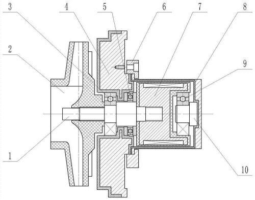
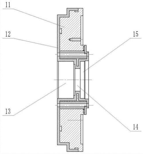
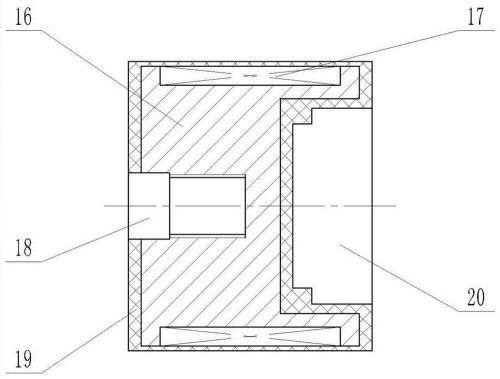
[0016] according to Figures 1 to 5 The specific structure of this invention is demonstrated in detail. The ceramic bearing fluorine plastic magnetic pump includes a main pump shaft 1 with an impeller 2 at one end; the other end of the main pump shaft 1 is provided with an inner magnetic steel 7 for cooperating with the outer magnetic assembly to rotate. Between the impeller 2 and the inner magnet 7, and outside the middle of the main pump shaft 1, a magnetic pump cover 4 is provided. The magnetic pump cover 4 is composed of a pump cover main body 11. The main shaft through hole 14 passing through; the pump cover main body 11 is provided with through holes and grooves for the fixing of the fluorine lining layer, and the main shaft through hole 14 is also provided with a rib for increasing the structural strength. The main shaft through hole 14 of the pump cover main body 11 is close to one end of the impeller 2, and is provided with a ball bearing installation groove I13 for ...


PUM


Abstract

A fluoroplastic magnetic drive pump with a ceramic bearing solves the problems that an existing magnetic drive pump is complex in structure, large in vibration, high in noise, frequent in maintenance and large in application limitation. Which comprises a main pump shaft with an impeller at one end, and is characterized in that inner magnetic steel is arranged at the other end of the main pump shaft; a main ceramic ball bearing is arranged on the side, close to the impeller, of the middle of the main pump shaft, and a ceramic thrust bearing is arranged on the side, close to the inner magnetic steel, of the middle of the main pump shaft. A magnetic pump cover is arranged between the impeller and the inner magnetic steel and on the outer side of the middle part of the main pump shaft; a sealing cover seat arranged outside the inner magnetic steel is connected with a pump cover of the magnetic drive pump through a pressing plate; a secondary pump shaft is arranged on the inner side of the end of the sealing cover seat, and a secondary ceramic ball bearing is arranged between the secondary pump shaft and the inner magnetic steel. The motor is reasonable in design, compact in structure, stable in operation, free of vibration, low in noise, long in service life and low in maintenance cost, and can operate for a long time without lubrication.

Description

technical field [0001] The invention belongs to the technical field of magnetic pumps, in particular to a ceramic bearing fluorine-plastic magnetic pump with stable operation, no vibration, low noise, long-term operation without lubrication, long service life and low maintenance cost. Background technique [0002] Most of the existing magnetic pumps and fluoroplastic magnetic pumps on the market use a pair of friction pairs between the rear of the impeller and the front of the inner magnetic steel, and a set of shaft sleeves and bushings between the pump shaft and the pump cover. . The magnetic pump and fluorine-plastic magnetic pump of such traditional structure will be severely worn between the friction pairs and between the shaft sleeve and the bushing after a short period of use. The increase of the magnetic force will lead to the eccentric rotation of the pump shaft, the large vibration of the pump body and the high noise, which will affect the use effect of the magnet...

Claims


Application Information

Patent Timeline
Patent Type & Authority Applications(China)
IPC IPC(8): F04D13/02F04D29/041F04D29/049
CPCF04D13/024F04D13/026F04D13/027F04D29/041F04D29/049
Inventor 虞淞
Owner 虞淞
Why Eureka
Try Eureka