Ultra-compact gearbox and generator integrated structure

A gearbox and generator technology, applied in wind power generation, belts/chains/gears, transmission boxes, etc., can solve the problems of material redundancy, structural function duplication, and structural dispersion of the gearbox and generator support structures, and achieve savings. The effect of weight, less cost, and compact connection structure

Pending Publication Date: 2022-06-07
南京轻机包装机械有限公司
0 Cites 0 Cited by

AI-Extracted Technical Summary

Problems solved by technology

[0004] The purpose of the present invention is to provide an integrated structure of an ultra-compact gearbox and a generator to solve the problem that the gearbox and the generator are connected through a coupling in the above-mentioned background ...

Method used

Please refer to Fig. 1 to Fig. 3, the present invention provides a kind of technical scheme: a kind of ultra-compact gearbox and generator integrated structure, comprise gearbox body 2 and generator body 3, one end of gearbox body 2 is placed Inside one end of the generator body 3, one end of the gearbox body 2 is fixed with a gearbox rear end cover 23. Through the designed gearbox rear end cover 23 and the generator body 3, the gearbox rear end cover 23 must bear the secondary The load of the planetary carrier 22 has to bear the load of the generator rotor 32. At the same time, the bearing structure of the generator body 3 adopts a single bearing structure, so that the generator rotor 32 completely acts on the rear end cover 23 of the gearbox, ensuring that the generator rotor 32 is coaxial with the gear box output shaft 24, saves some parts of the gear box and the generator, reduces weight, saves cost, and reduces load. One end of the gear box rear end cover 23 is fixed with a secondary planet carrier 22, and the gear box body 2 is provided with a low-speed shaft at one end, and the inside of the generator body 3 is provided with a stator assembly 31. The stator assembly 31 of the generator is designed, and the stator assembly 31 is connected to the middle body of the gearbox body 2 through fasteners, so that The center of gravity of the generator is further forward, and the structure is more compact. The inside of the stator assembly 31 is provided with a generator rotor 32, one end of the generator rotor 32 is attached to the rear end cover 23 of the gearbox, and the inside of the generator rotor 32 is provided with a bearing outer ring 33, the inner side of bearing outer ring 33 is provided with bearing inner ring 34, the ends of bearing inner ring 34 and bearing outer ring 33 are provided with drive cover plate 36, and the inner center of gearbox body 2 is provided with gearbox output shaft 24 , and one end of the gearbox output shaft 24 is placed inside the bearing inner ring 34, the gearbox output shaft 24 and the driving cover plate 36 are fixed by screws, the end of the generator body 3 is connected with a tube bearing 38, and the gearbox output shaft 24 A threading pipe 1 runs through the inside of the threading pipe 1. One end of the threading pipe 1 is installed on the low-speed shaft, a...

Abstract

The invention discloses an ultra-compact gearbox and generator integrated structure which comprises a gearbox body and a generator body, one end of the gearbox body is arranged in one end of the generator body, a gearbox rear end cover is fixed to one end of the gearbox body, a secondary planet carrier is fixed to one end of the gearbox rear end cover, and a secondary planet carrier is fixed to the other end of the secondary planet carrier. A low-speed shaft is arranged at one end in the gearbox body; by designing the generator body, the gear box body and the gear box rear end cover, the connecting structure of the gear box and the generator is more compact, the weight is saved, the cost is low, meanwhile, the generator rotor is directly installed on the gear box rear end cover, the centering requirement can be completely met through machining, and the machining efficiency is improved. The generator centering link in the assembling process is omitted, assembling working hours are saved, the generator and the gear box are integrated, the gravity center of the generator is in the front, a gear box torque arm can be omitted, and the generator is directly connected with the bearing seat through the front end connecting end cover.

Application Domain

Technology Topic

Electric generatorGravity center

Image

  • Ultra-compact gearbox and generator integrated structure
  • Ultra-compact gearbox and generator integrated structure
  • Ultra-compact gearbox and generator integrated structure

Examples

  • Experimental program(1)

Example Embodiment

[0020] Example
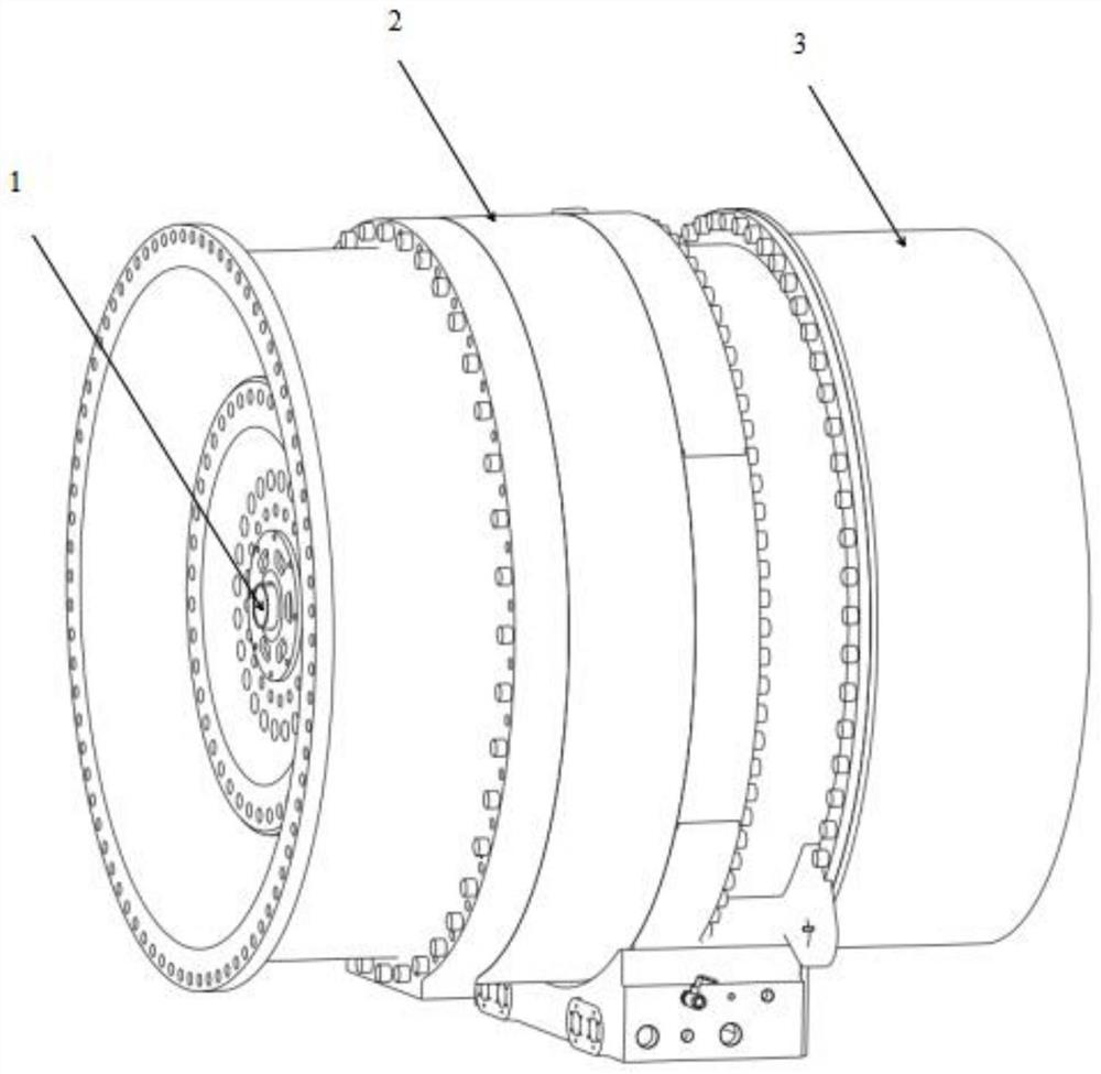
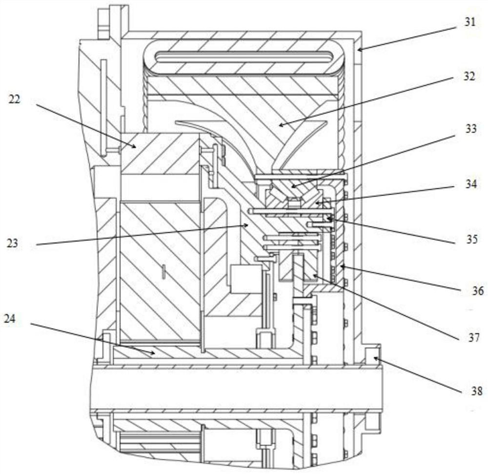
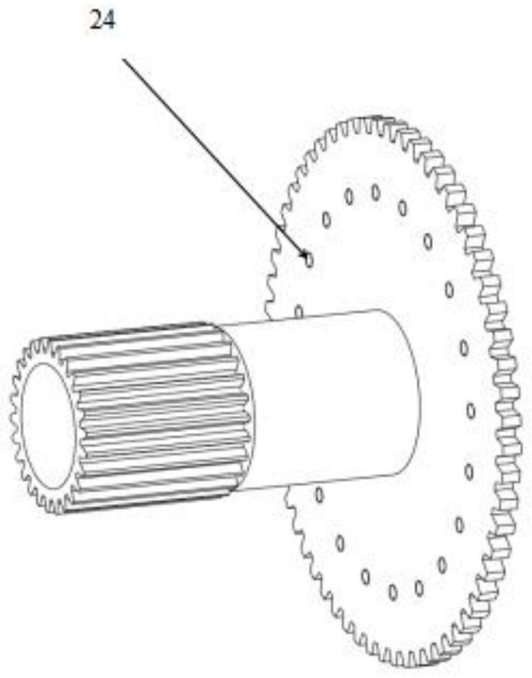
[0021] see Figure 1 to Figure 3 , the present invention provides a technical solution: an ultra-compact gearbox and generator integrated structure, including a gearbox body 2 and a generator body 3, one end of the gearbox body 2 is placed inside one end of the generator body 3, the gear box One end of the box body 2 is fixed with a rear end cover 23 of the gearbox. Through the designed rear end cover 23 of the gearbox and the generator body 3, the rear end cover 23 of the gearbox must bear the load of the secondary planetary carrier 22 and the generator. At the same time, the bearing structure of the generator body 3 adopts a single bearing structure, so that the generator rotor 32 completely acts on the rear end cover 23 of the gearbox, ensuring that the generator rotor 32 is coaxial with the gearbox output shaft 24, The gearbox and some parts of the generator are omitted, which reduces the weight, cost and load. One end of the rear end cover 23 of the gearbox is fixed with a secondary planetary carrier 22, and one end of the inner end of the gearbox body 2 is provided with a low-speed shaft to generate electricity. The interior of the machine body 3 is provided with a stator assembly 31. Through the designed stator assembly 31 of the generator, the stator assembly 31 is connected to the middle body of the gearbox body 2 through fasteners, so that the center of gravity of the generator is further forward, and the structure is more The generator rotor 32 is arranged inside the stator assembly 31, one end of the generator rotor 32 is fitted with the rear end cover 23 of the gearbox, the inside of the generator rotor 32 is arranged with a bearing outer ring 33, and the inner side of the bearing outer ring 33 is arranged There is a bearing inner ring 34, the ends of the bearing inner ring 34 and the bearing outer ring 33 are provided with a drive cover plate 36, the inner center of the gearbox body 2 is provided with a gearbox output shaft 24, and one end of the gearbox output shaft 24 is located Inside the bearing inner ring 34 , the gearbox output shaft 24 and the drive cover 36 are fixed by screws, the end of the generator body 3 is connected with a tube bearing 38 , and the inside of the gearbox output shaft 24 is penetrated by a threading pipe 1 , and the threading pipe One end of 1 is installed on the low-speed shaft, the other end of the threading pipe 1 is installed on the tube bearing 38, a plurality of bosses are fixed on the inner side of the rear end cover 23 of the gearbox, and a brake 37 is installed on the bosses. The output shaft 24 and the brake 37, the gearbox output shaft 24 can not only transmit torque, but also realize the braking effect through the brake 37. The outer side is also designed with a toothed structure, which is convenient for later electric cranking.
[0022] In this embodiment, preferably, a bearing retaining ring 35 is provided between the bearing outer ring 33 and the drive cover plate 36 , and the designed bearing retaining ring 35 is connected with the rear end cover 23 of the gearbox by screws, and the bearing inner ring 34 is connected with screws. Compression is carried out to form a whole, the bearing retaining ring 35 is connected with the rear end cover 23 of the gearbox by screws, the bearing inner ring 34 and the bearing outer ring 33 are sleeved on the rear end cover 23 of the gearbox, and the bearing inner ring 34 and the bearing Rollers are arranged between the outer ring 33, the drive cover 36 and the gearbox output shaft 24 are connected by screws, and the designed drive cover 36 and the gearbox output shaft 24 are connected by screws, so as to drive the generator rotor. 32 rotates, and the longitudinal section of the drive cover 36 is a circular structure, the longitudinal section of the gearbox output shaft 24 is a T-shaped structure, and one end surface of the gearbox output shaft 24 is provided with a tooth slot, and the gearbox output shaft 24 The outer wall of the other end is provided with a spline.
[0023] The working principle and use process of the present invention: when the present invention is installed, the rear end cover 23 of the gear box is installed on one end of the gear box body 2. After the installation of the rear end cover 23 of the gear box is completed, the gear box body 2 is turned over to make the axis perpendicular to the On the ground, put the generator rotor 32 into the gear box body 2, fix it with tooling, heat the bearing inner ring 34, and together with the rollers and the bearing outer ring 33, put it into the gear box rear end cover 23, and connect the bearing through the connecting piece. The retaining ring 35 is fixed with the rear end cover 23 of the gearbox and presses the inner ring 34 of the bearing to form an integral body. The lower part of the brake 37 is fixed on the boss, and the output shaft 24 of the gearbox is placed vertically to make the splines mesh correctly. The upper part of the brake 37 is connected with the lower part through the connecting piece, and then the driving cover plate 36, the bearing outer ring 33 and the generator rotor 32 are connected rigidly in rotation, and finally the gearbox output shaft 24 is connected with the driving cover plate 36. Through the cooperation and assembly of the gearbox rear end cover 23, the gearbox body 2 and the generator body 3, the connection structure is more compact, the weight is saved, and the cost is reduced. The generator rotor 32 is directly installed on the rear end cover 23 of the gearbox, The centering requirements can be completely guaranteed by machining, which saves the generator centering link in the assembly process and saves assembly man-hours. At the same time, the generator body 3 has been integrated with the gearbox body 2, and its center of gravity is forward, so the gear can be omitted. The box torque arm is directly connected to the bearing seat through the front end connecting cover.

PUM

no PUM

Description & Claims & Application Information

We can also present the details of the Description, Claims and Application information to help users get a comprehensive understanding of the technical details of the patent, such as background art, summary of invention, brief description of drawings, description of embodiments, and other original content. On the other hand, users can also determine the specific scope of protection of the technology through the list of claims; as well as understand the changes in the life cycle of the technology with the presentation of the patent timeline. Login to view more.

Similar technology patents

Mechanical ultrasonic cleaning machine

InactiveCN110142254ACompact connectionSimple structural connectionCleaning using liquidsImpellerMegasonic cleaning
Owner:攸潇潇

Grinding device used in flour-milling machines

InactiveCN108940453ACompact connectionEasy to installGrain treatmentsEngineeringGrinding process
Owner:王品芳

Waterproof acoustics structure

Owner:CHENGDU LYUDI TECH

Lifting hanger of mechanical equipment

InactiveCN109132846ACompact connectionEasy to useLoad-engaging elementsEngineeringWire rope
Owner:郑州骏弘机电科技有限公司

Classification and recommendation of technical efficacy words

  • Reduce weight
  • Compact connection

Nonwoven material for acoustic insulation, and process for manufacture

ActiveUS20100066121A1Improve acoustic propertiesReduce weightCeilingsWallsFibrous layerAirflow
Owner:GLATFELTER CORP

Metal-to-metal sealing tieback connector

ActiveCN101769146AEasy to connect and sealCompact connectionEngine sealsFluid removalCasing hangerLine tubing
Owner:BC P INC CHINA NAT PETROLEUM CORP +1

Hydraulically-driven reciprocating air compressor

Owner:东莞海特帕沃液压科技有限公司

Marine water quality detection system

InactiveCN109001403ACompact connectionEasy to useTesting waterMarine water qualityEngineering
Owner:郑州贯奥仪器仪表有限公司
Why Eureka
Try Eureka