
Monitoring camera for security and protection

A monitoring camera and camera technology, which is applied in the field of cameras, can solve the problems of monitoring dead angles, storing too much data, overheating of devices, etc., and achieve the effects of improving service life, expanding monitoring range, and avoiding monitoring dead angles

Pending Publication Date: 2022-06-07
谢华东
View PDF13 Cites 0 Cited by
  • Summary
  • Abstract
  • Description
  • Claims
  • Application Information

AI Technical Summary

Problems solved by technology

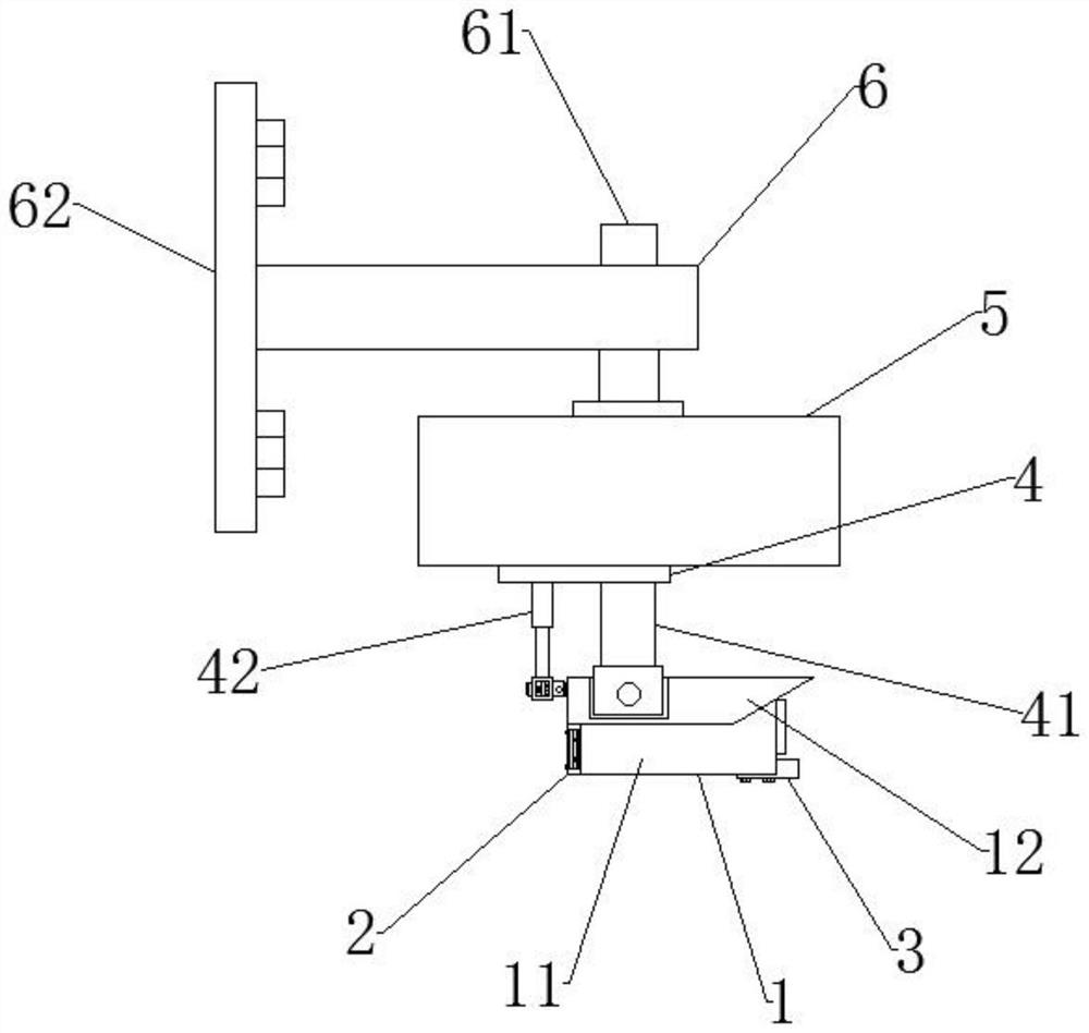
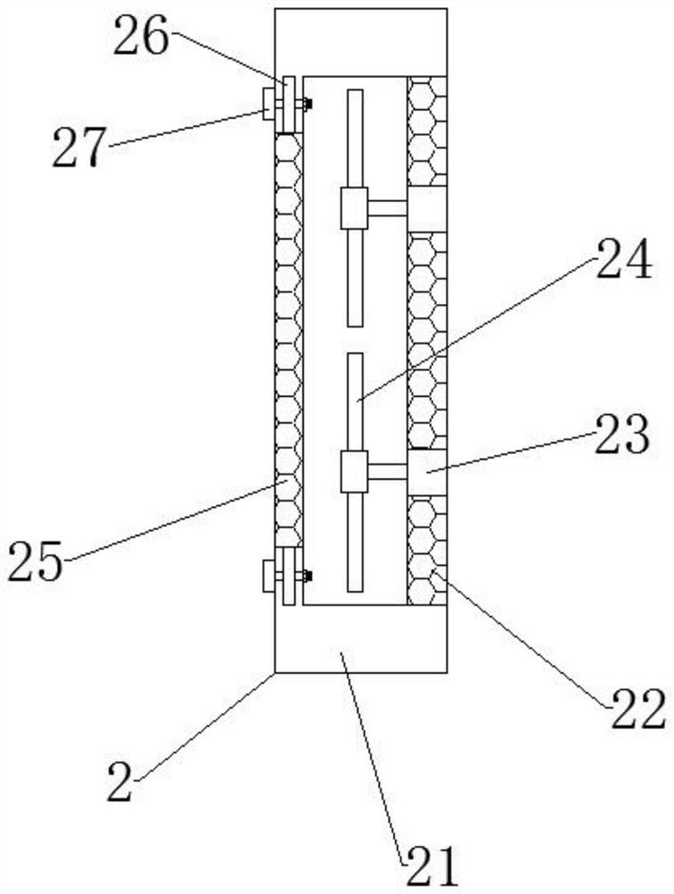
[0006] The present invention provides a monitoring camera for security, one of the purposes is to have the effect of cooling the camera, and to solve the problem that the existing monitoring camera usually stores too much data after a long time of use, and the device is prone to overheating, and then It will reduce the smoothness and clarity of the camera's shooting picture, and may even cause its direct damage; another purpose is to solve the problem that the existing surveillance cameras are usually directly fixed on the connecting seat, the camera cannot be moved, and its monitoring The range is limited, and it is easy to have dead spots in monitoring, which may lead to the problem of theft accidents, so as to achieve the effect of improving the monitoring range of the camera

Method used


Image

  • Monitoring camera for security and protection
  • Monitoring camera for security and protection
  • Monitoring camera for security and protection

Examples


Embodiment Construction

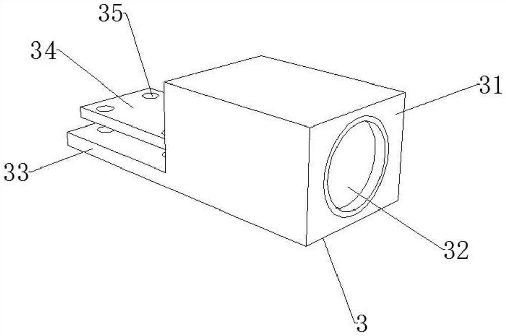
[0036] Attached to the following Figure 1-8 The principles and features of the present invention are described. The invention is described in more detail by way of example in the following paragraphs with reference to the accompanying drawings, advantages and features of the invention will become more apparent from the following description and claims. It should be noted that, the accompanying drawings are all in a very simplified form and in inaccurate scales, and are only used to facilitate and clearly assist the purpose of explaining the embodiments of the present invention.

[0037] It should be noted that when a component is referred to as being "fixed to" another component, it can be directly on the other component or there may also be a centered component. When a component is considered to be "connected" to another component, it may be directly connected to the other component or there may be a co-existence of an intervening component. When a component is considered ...


PUM


Abstract

The invention discloses a security monitoring camera, and relates to the technical field of cameras, the security monitoring camera comprises a main body mechanism, the main body mechanism comprises a camera, the top end of the camera is fixedly connected with a protective shell, and the left side of the camera is provided with a heat dissipation mechanism. The fan blades are driven by the driving motor to rotate, so that the camera can be cooled, the camera is prevented from being in a high-temperature state after working for a long time, burnout and damage are prevented, the service life of the device is prolonged, the connecting seat is mounted on the bracket through the fixing buckle, and then the rotating motor drives the rotating gear to rotate, so that the camera can be conveniently and rapidly cooled. Through the interaction of a rotating gear and a butt joint rack, a limiting plate and a connector can be driven to move along a movable groove in a semicircular plate, and then the camera is driven to move, so that the monitoring range of the camera can be enlarged, monitoring dead angles of the camera are avoided, and a theft accident is prevented; therefore, the use safety of the camera is improved.

Description

technical field [0001] The invention relates to the technical field of cameras, in particular to a security monitoring camera. Background technique [0002] The camera is a video input device, a type of closed-circuit television, and is widely used in video conferencing, telemedicine and real-time monitoring. After the image is collected, the image is processed by the photosensitive component circuit and the control component in the camera and converted into a digital signal that can be recognized by the computer, and then connected to the computer through the parallel port and USB, and then the image is restored by the software. form a picture. [0003] The following problems exist for the prior art: [0004] 1. Existing surveillance cameras generally store too much data after long-term use, which is prone to overheating of the device, which will reduce the smoothness and clarity of the camera's captured images, and may even lead to direct damage; [0005] 2. The existin...

Claims


Application Information

Patent Timeline
Patent Type & Authority Applications(China)
IPC IPC(8): F16M13/02F16M11/04F16M11/10F16M11/18H04N5/225G03B17/55
CPCF16M13/02F16M11/046F16M11/10F16M11/18G03B17/55H04N23/50
Inventor 谢华东
Owner 谢华东
Learn More