Method and equipment for monitoring state of low-voltage power transmission and distribution line in non-contact manner

A non-contact technology for power transmission and distribution lines, applied in the field of line status judgment, can solve the problems of inconvenient grid companies to quickly locate and solve line faults, increase property losses of companies and users, and achieve the effect of reducing property losses and realizing intelligence

Pending Publication Date: 2022-06-07
南京亿数信息科技有限公司
View PDF0 Cites 0 Cited by
  • Summary
  • Abstract
  • Description
  • Claims
  • Application Information

AI Technical Summary

Problems solved by technology

[0005] The purpose of the present invention is to provide a non-contact method and equipment for monitoring the state of low-voltage transmission and distribution lines to solve the existing problems: it is not convenient for the power grid company to quickly locate and solve the line fault problem, which increases the property loss of the company and users

Method used


Image

  • Method and equipment for monitoring state of low-voltage power transmission and distribution line in non-contact manner

Examples


Embodiment 1

[0022] A method for non-contact monitoring of the state of low-voltage transmission and distribution lines, comprising at least the following steps:

[0023] Set up monitoring equipment on the nodes that need to be monitored;

[0024] During the detection process, the monitoring equipment monitors the voltage and current on the transmission and distribution lines of the low-voltage power grid through the principle of electromagnetic induction, and forms feedback;

[0025] Through the feedback, it is then judged whether the line is faulty or whether it is the source of the fault.

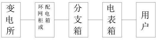
[0026] Setting monitoring equipment at nodes that need to be monitored includes at least the following locations: setting monitoring equipment at nodes between substations and multiple ring network cabinets and distribution stations, and between ring network cabinets, distribution stations and multiple branch boxes A monitoring device is set at the node of the device, a monitoring device is set at t...

Embodiment 2

[0028] A device for non-contact monitoring of the state of a low-voltage transmission and distribution line, used in the above-mentioned embodiments, includes a line voltage monitoring circuit device and a line current monitoring circuit device, and the line voltage monitoring circuit device and the line current monitoring circuit device both include a housing and a composite circuit, the inner side of the housing is provided with a composite circuit preferably

[0029] The composite circuit includes electromagnetic induction circuit, circuit amplification circuit, threshold judgment circuit and signal transmission circuit. The electromagnetic induction circuit, circuit amplification circuit, threshold judgment circuit and signal transmission circuit are electrically connected. The electromagnetic induction circuit is used for induction triggering and production. The electrical signal, the circuit amplifying circuit is used to amplify the electrical signal of the electromagneti...


PUM


Abstract

The invention discloses a method and equipment for monitoring the state of a low-voltage power transmission and distribution line in a non-contact mode, and relates to the technical field of line state judgment. The method at least comprises the following steps that a monitoring device is arranged at a node needing to be monitored, the monitoring device monitors voltage and current on a low-voltage power grid power transmission and distribution line through the electromagnetic induction principle in the detection process, and feedback is formed. The method can be applied to a low-voltage range of 220-11 kilovolts and a current range of 40-1000 amperes by adjusting induced current and voltage thresholds, encompasses all line ends from a substation to a final 220V power user, quickly positions and solves a line fault problem for a power grid company, reduces property loss of the company and the user, and can be applied to a power grid company. According to the method, the existing line can be quickly upgraded, and the intelligence of the existing power grid line is realized under the conditions of not influencing the original line architecture, not changing the original electric power facility, not interfering the power grid user under the operating line and the like.

Description

technical field [0001] The invention relates to the technical field of line state determination, in particular to a method and device for non-contact monitoring of the state of a low-voltage power transmission and distribution line. Background technique [0002] At present, there is no suitable monitoring means and equipment in the field of low-voltage transmission and distribution lines of the State Grid; if a line failure occurs, the faulty user is generally notified to the power grid company, and the power grid company sends maintenance personnel to gradually find the fault point and eliminate the fault. The efficiency is very low during this period. , the problem solving cycle is long, and it will bring great losses to the users on the faulty line; [0003] In addition, the existing intelligent air switch can only judge the opening and closing status of the line, but cannot determine the source of the fault point. In addition, the intelligent air switch needs to replace ...

Claims


Application Information

Patent Timeline
IPC IPC(8): G01R31/08
CPCG01R31/085Y02E60/00
Inventor 韩加国滕远志田玉
Owner 南京亿数信息科技有限公司
Why Eureka
Try Eureka