Self-starting synchronous reluctance motor rotor and motor

A synchronous reluctance motor and self-starting technology, which is applied in the direction of synchronous motors, electromechanical devices, electrical components, etc. for single-phase current, can solve the problems of large torque ripple and large current harmonics, and achieve the solution of current harmonics Larger, lower harmonics, and lower cogging effects

Pending Publication Date: 2022-06-07
GREE ELECTRIC APPLIANCES INC
View PDF1 Cites 0 Cited by
  • Summary
  • Abstract
  • Description
  • Claims
  • Application Information

AI Technical Summary

Problems solved by technology

[0006] Therefore, the technical problem to be solved by the present invention is to overcome the defects of large current harmonics and large torque ripple in the self-starting reluctance motor in the prior art, thereby providing a self-starting synchronous reluctance motor rotor and motor

Method used


Image

  • Self-starting synchronous reluctance motor rotor and motor
  • Self-starting synchronous reluctance motor rotor and motor
  • Self-starting synchronous reluctance motor rotor and motor

Examples


Embodiment Construction

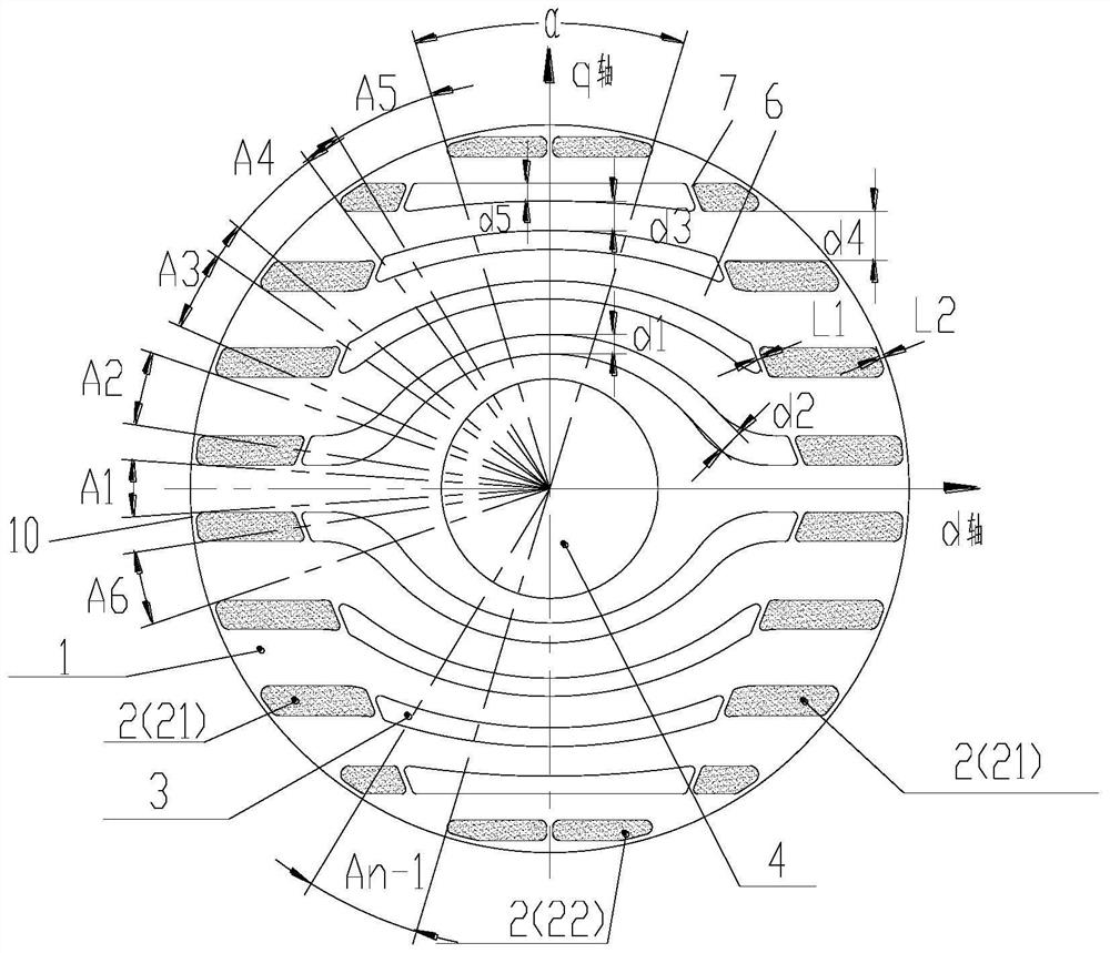
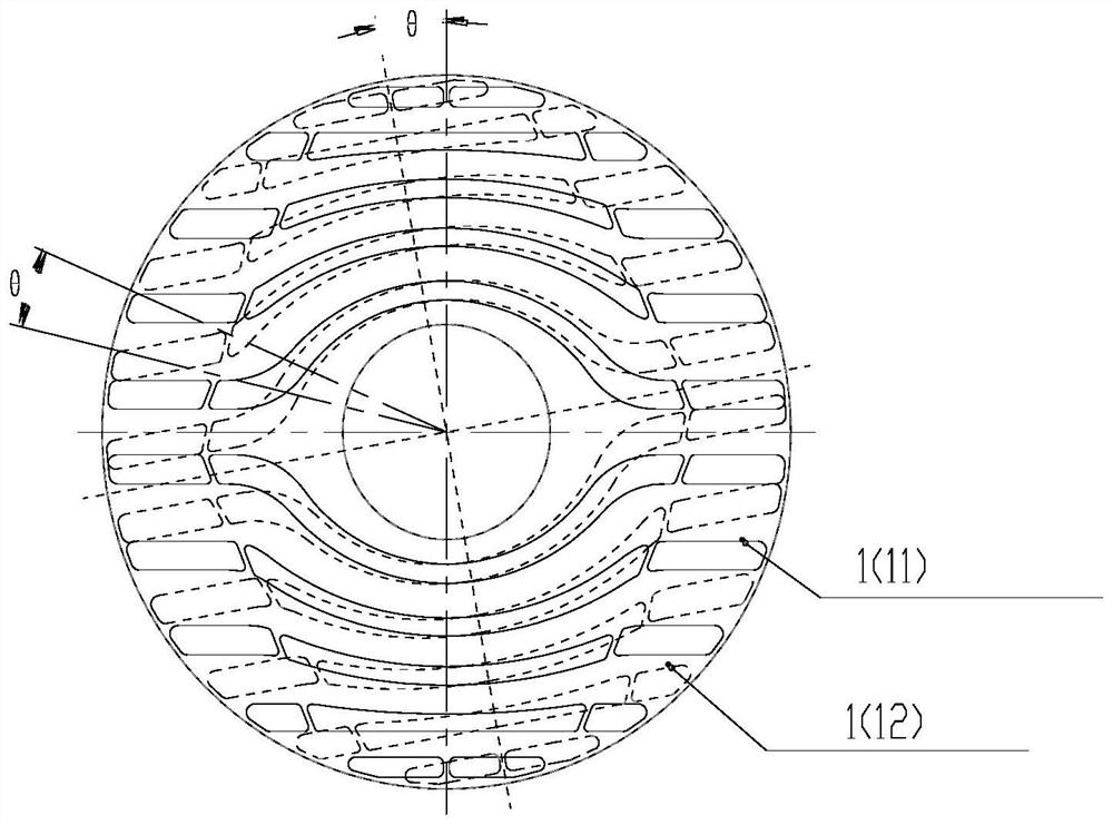
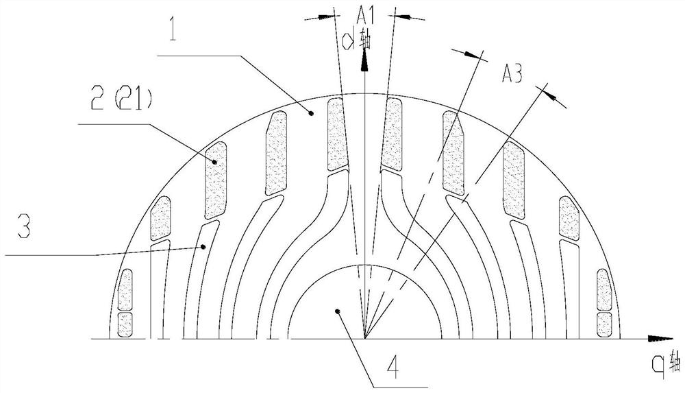
[0034] like Figure 1-5 As shown, the present invention provides a self-starting synchronous reluctance motor rotor, which includes a rotor core, which is formed by laminating a plurality of rotor punches 1, and the rotor punches 1 are provided with filling grooves 2. The slit slot 3 and the shaft hole 4, in the direction from one axial end of the rotor to the other axial end, the next rotor punching piece in the two adjacent rotor punching pieces 1 is relative to the previous rotor punching. The blade rotates around the rotor center by a preset angle, and the rotation directions of all the rotor blanks 1 are in the same direction; so that the rotor blanks located at the other end of the axial direction rotate around the rotor center relative to the rotor blanks located at one end of the axial direction. The angle is θ, where θ>0, and θ is the rotor chute.

[0035] The rotor of the present invention is formed by laminating rotor punching sheets with a specific structure. The ...


PUM


Abstract

The invention provides a self-starting synchronous reluctance motor rotor and a motor, the self-starting synchronous reluctance motor rotor comprises a rotor iron core, the rotor iron core is formed by laminating a plurality of rotor punching sheets, each rotor punching sheet is provided with a filling groove, a slit groove and a shaft hole, and the filling grooves, the slit grooves and the shaft hole are arranged in the direction from one axial end of the rotor to the other axial end of the rotor. The next rotor punching sheet of the two adjacent rotor punching sheets rotates around the center of the rotor by a preset angle relative to the previous rotor punching sheet, and the rotation directions of all the rotor punching sheets face the same direction; the rotation angle of the rotor punching sheet at the other axial end around the center of the rotor relative to the rotor punching sheet at one axial end is theta, theta is larger than 0, and theta is a rotor skewed slot. According to the invention, the position relation between the magnetic conduction channel and the stator tooth groove can be continuously changed in the axial direction, and an air gap harmonic magnetic field caused by the motor stator tooth groove effect can be axially offset, so that the tooth groove effect is effectively reduced, and harmonic waves are reduced.

Description

technical field [0001] The invention relates to the technical field of motors, in particular to a self-starting synchronous reluctance motor rotor and a motor. Background technique [0002] The self-starting synchronous reluctance motor combines the structural characteristics of the induction motor and the reluctance motor. The torque is generated by the squirrel cage induction to realize the start, and the reluctance torque is generated by the rotor inductance difference to realize the constant speed operation. It can be directly connected to the power supply to realize the start operation. Compared with the asynchronous starting permanent magnet motor, the self-starting synchronous reluctance motor has no rare earth permanent magnet material and no demagnetization problem. The motor has low cost and good reliability. [0003] However, there are many magnetic conduction channels on the rotor of the self-starting reluctance motor, which lead to large harmonics of the motor m...

Claims


Application Information

Patent Timeline
Patent Type & Authority Applications(China)
IPC IPC(8): H02K1/22H02K19/14
CPCH02K1/22H02K19/14H02K2213/03
Inventor 史进飞李霞肖勇王杜李莹
Owner GREE ELECTRIC APPLIANCES INC
Why Eureka
Try Eureka