Mobile operation terminal based on Beidou satellite communication
A satellite communication and mobile operation technology, applied in the direction of sustainable communication technology, advanced technology, climate sustainability, etc., can solve the problems of fixed handle structure, inconvenient carrying by field technicians, and inability of the handle to stably support the tilt of the mobile terminal, etc. , to achieve the effect of not easy to lose and slip, stable support
- Summary
- Abstract
- Description
- Claims
- Application Information
AI Technical Summary
Problems solved by technology
Method used
Image
Examples
Embodiment 1
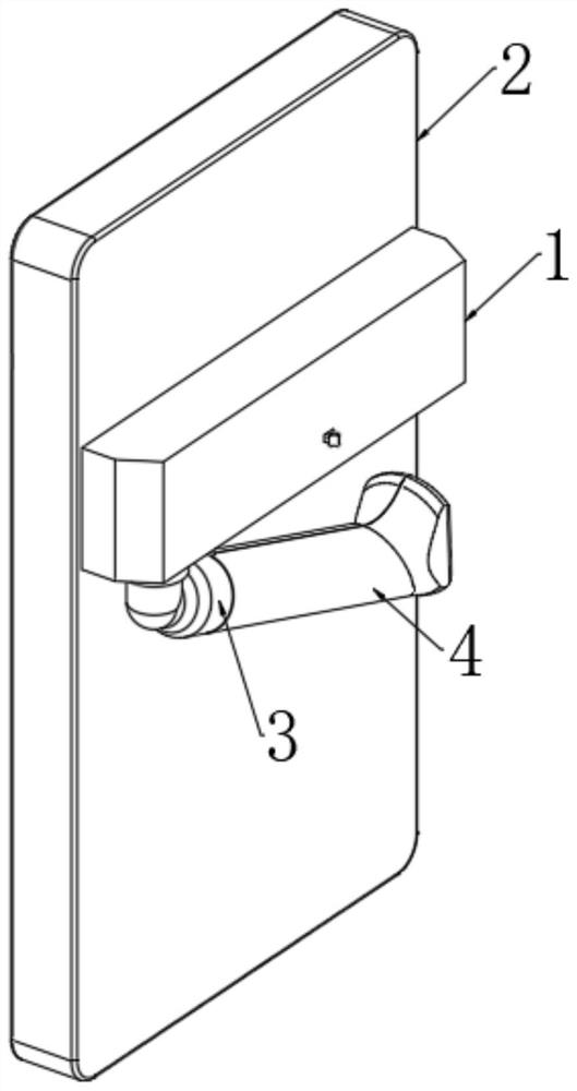
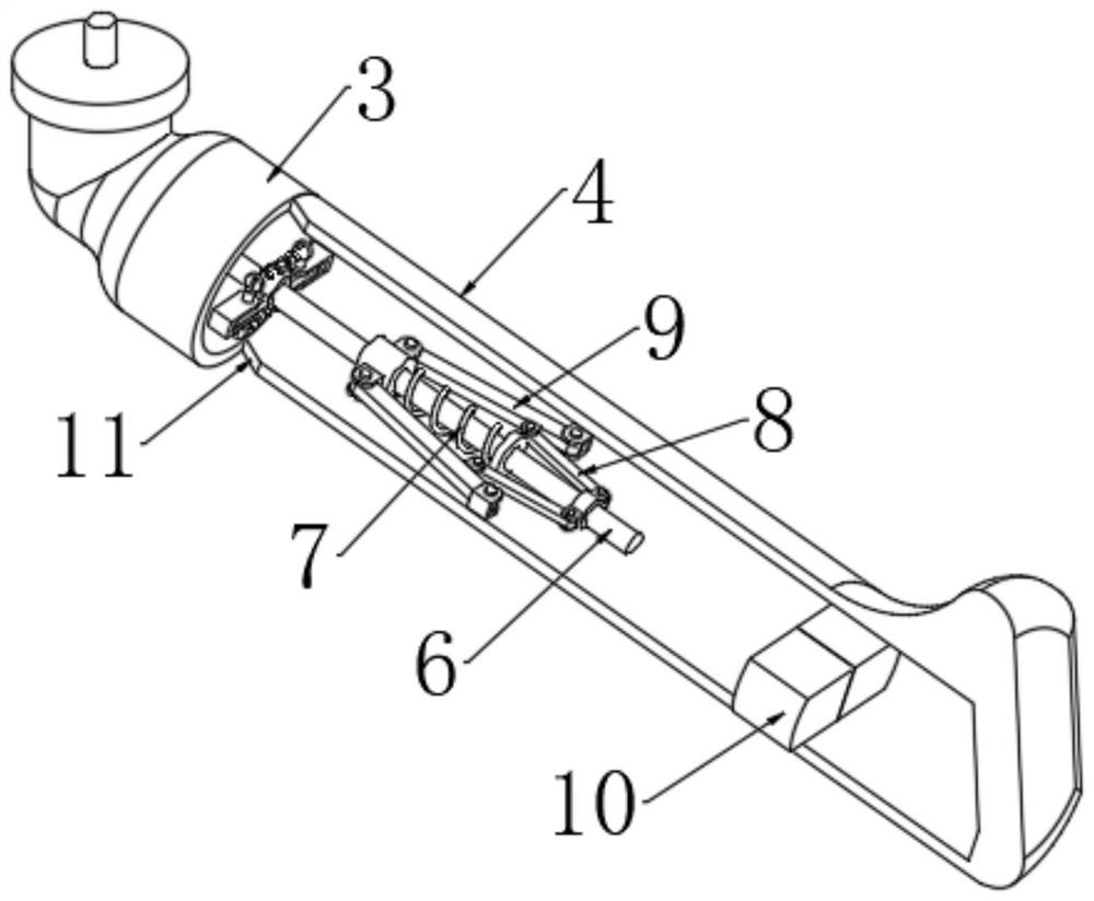
[0037] Refer to the attached Figure 1-11 , A mobile operation terminal based on Beidou satellite communication, including a terminal body 2 and a casing 1, the casing 1 is fixed on the side wall of the terminal body 2, the casing 1 is fixedly connected with a partition 25, and one side of the partition 25 is connected with a Transmission mechanism, the transmission mechanism is connected with a handle, the handle is composed of an elbow 20, a sleeve 3 and two symmetrically arranged shells 4, the opposite sides of the two shells 4 are jointly connected with a connecting mechanism, and the corners of the shell 4 are provided with Inclined surface 11, two rectangular rods 22 parallel to each other are fixedly connected to the inner side of the casing 1, and one end of the two rectangular rods 22 is fixedly connected to one side of the partition plate 25. The casing 1 is provided with a mounting plate 23. The mounting plate The side wall of 23 is sleeved with the rod wall of the ...
Embodiment 2
[0039] Embodiment 2: What is different based on Embodiment 1 is;
[0040] Refer to the attached Figure 6-8 , the transmission mechanism includes a first gear ring 24, the first gear ring 24 is fixedly connected with the shaft wall of the rotating shaft 5, the upper end of the rotating shaft 5 is rotatably connected with one side of the mounting plate 23 through a rolling bearing, and one side of the mounting plate 23 passes through the first ball bearing. A support shaft is rotatably connected, a first gear 28 and a second gear 27 are fixedly connected to the shaft wall of the support shaft, the first gear 28 is meshed with the first ring gear 24, and one side of the second gear 27 is meshed with a third gear 29 , the side wall of the mounting plate 23 is rotatably connected with a transmission shaft through the second ball bearing, one end of the transmission shaft is coaxially and fixedly connected with the upper end of the third gear 29, and the upper end of the transmissi...
Embodiment 3
[0042] Embodiment 3: The difference based on Embodiment 1 is;
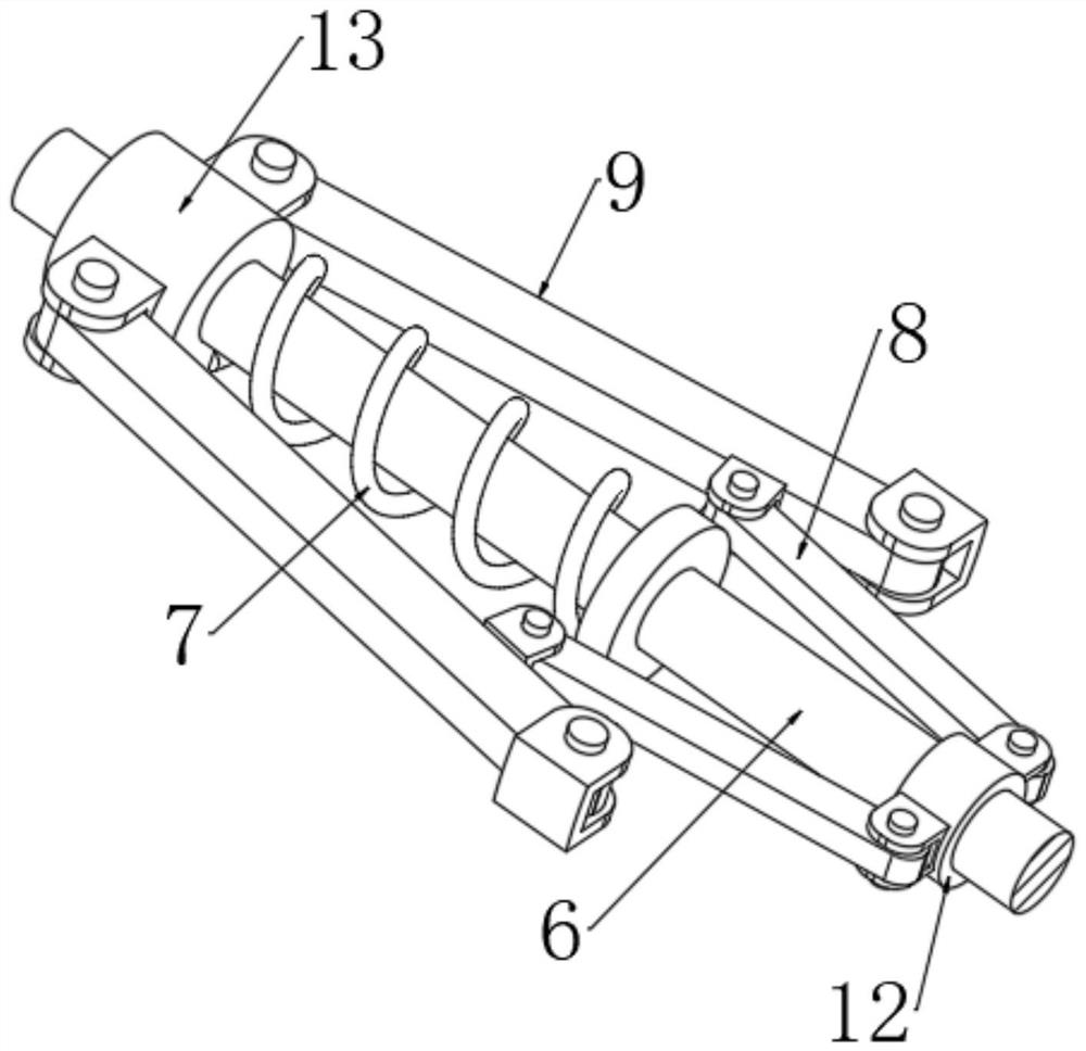
[0043] Refer to the attached Figure 2-5 , the connection mechanism includes a sleeve 13 and a sliding sleeve 16, the sleeve 13 and the sliding sleeve 16 are both sleeved on the rod wall of the guide rod 6, and the pipe wall of the sleeve 13 is rotated through the first connecting shaft. There are two symmetrically distributed The end of the two transmission rods 9 away from the sleeve 13 is connected to the opposite side of the two outer shells 4 through the second connecting shaft respectively. The rod wall of the guide rod 6 is sleeved with a first tension spring 7 , one end of the first tension spring 7 is fixedly connected to the sleeve 13, the other end of the first tension spring 7 is fixedly connected to a limit ring, and the limit ring is fixedly connected to the rod wall of the guide rod 6, and the side wall of the sliding sleeve 16 is fixedly connected. Two rectangular frames 17 are symmetrically and f...
PUM
 Abstract
Description
Claims
Application Information
 - R&D
- Intellectual Property
- Life Sciences
- Materials
- Tech Scout
- Unparalleled Data Quality
- Higher Quality Content
- 60% Fewer Hallucinations
Browse by: Latest US Patents, China's latest patents, Technical Efficacy Thesaurus, Application Domain, Technology Topic, Popular Technical Reports.
© 2025 PatSnap. All rights reserved.Legal|Privacy policy|Modern Slavery Act Transparency Statement|Sitemap|About US| Contact US: help@patsnap.com


