Balancing weight mechanism of engineering machinery, engineering machinery and shifting method of balancing weight mechanism

A technology of construction machinery and counterweights, which is applied in the direction of counterweights, cranes, mechanical equipment, etc., to achieve the effect of increasing the tipping moment, meeting the width requirements, and increasing the rotation range

Active Publication Date: 2022-06-10
XUZHOU HEAVY MASCH CO LTD
View PDF5 Cites 1 Cited by
  • Summary
  • Abstract
  • Description
  • Claims
  • Application Information

AI Technical Summary

Problems solved by technology

In order to improve the hoisting performance of the crane, it is necessary to continuously increase the weight of the counterweight to increase the anti-overturning moment of the crane, thus causing the continuous increase of manufacturing and transportation costs, and more importantly, limiting the working conditions of the crane in many small working spaces
[0003]In the prior art, fixed counterweights are generally used, and because their positions are relatively fixed, they cannot be adjusted according to the working environment during the operation
In addition, there are some counterweights that use horizontal slide rail mechanisms, but their structures are more complex, their reliability is poor, and the degree of displacement of the counterweight is limited.

Method used


Image

  • Balancing weight mechanism of engineering machinery, engineering machinery and shifting method of balancing weight mechanism
  • Balancing weight mechanism of engineering machinery, engineering machinery and shifting method of balancing weight mechanism
  • Balancing weight mechanism of engineering machinery, engineering machinery and shifting method of balancing weight mechanism

Examples


Embodiment Construction

[0037]The relative arrangements of components and steps, numerical expressions and numerical values ​​set forth in these embodiments do not limit the scope of the present application unless specifically stated otherwise. At the same time, it should be understood that, for the convenience of description, the sizes of the various parts shown in the drawings are not drawn according to the actual proportional relationship. Techniques, methods and devices known to those of ordinary skill in the relevant art may not be discussed in detail, but where appropriate, techniques, methods and devices should be considered part of the description. In all examples shown and discussed herein, any specific values ​​should be construed as illustrative only, and not as limiting. Therefore, other examples of the exemplary embodiment may have different values. It should be noted that like numerals and letters denote like items in the following figures, therefore, once an item is defined in one fig...


PUM


Abstract

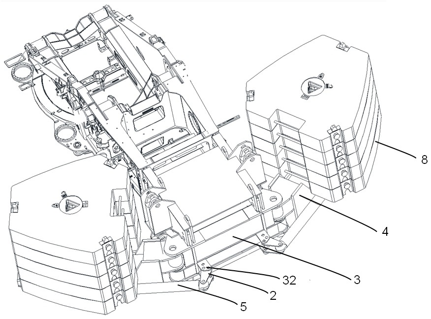
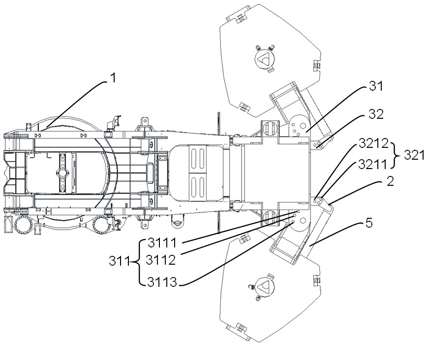
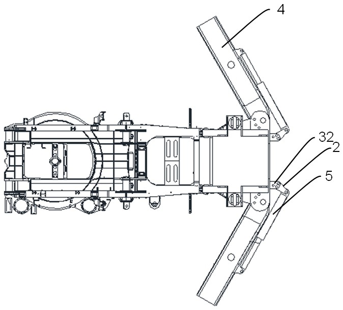
The invention discloses a counterweight mechanism, engineering machinery and a counterweight mechanism displacement method. The balance weight mechanism comprises a base frame, a balance weight, a bracket, a swing rod and a telescopic mechanism. The base frame is installed on the rear side of a rotary platform of the engineering machine. The bracket is used for bearing the balance weight, and one end of the bracket is rotatably connected to the base frame. The first end of the swing rod is rotatably connected to the base frame. The first end of the telescopic mechanism is rotatably connected to the bracket, and the second end of the telescopic mechanism is rotatably connected to the second end of the swing rod. The first end and the second end of the telescopic mechanism are telescopically arranged to drive the bracket and the swing rod to rotate relative to the base frame so as to adjust the position of the balance weight. According to the scheme, the rotating range of the bracket is enlarged by arranging the swing rod, and therefore the gravity center adjusting range of the balance weight is enlarged.

Description

technical field [0001] The present application relates to the field of construction machinery, in particular to a counterweight mechanism of construction machinery, construction machinery and a method for displacing the counterweight mechanism. Background technique [0002] Cranes are widely used in the hoisting operations of wind farms, large petrochemical projects, large bridges and other projects, and are also increasingly used in the construction of cities and factories. Customers have more and more requirements for the performance and space adaptability of cranes. high. In order to improve the lifting performance of the crane, it is necessary to continuously increase the weight of the counterweight to increase the anti-overturning moment of the crane, which results in continuous increases in manufacturing and transportation costs, and more importantly, limits the working conditions of the crane in many small working spaces. [0003] In the prior art, a fixed balance we...

Claims


Application Information

Patent Timeline
Patent Type & Authority Applications(China)
IPC IPC(8): B66C23/74F16F15/28
CPCB66C23/74F16F15/00Y02E10/72
Inventor 单增海付玉琴刘乐张伟龙邓海青
Owner XUZHOU HEAVY MASCH CO LTD
Why Eureka
Try Eureka