
Control system of chargeable battery and its control method

A technology of rechargeable battery and battery unit, which is applied in secondary battery charging/discharging, arrangement of multiple synchronous batteries, secondary battery, etc., and can solve the problems of wasting large power and long time

Inactive Publication Date: 2004-04-14
吴世侊
View PDF1 Cites 0 Cited by
  • Summary
  • Abstract
  • Description
  • Claims
  • Application Information

AI Technical Summary

Problems solved by technology

However, according to this prior invention, the amount of electricity wasted in the individual discharge process is very large, and it takes a long time to fully discharge all the battery cells in different energy states

Method used


Image

  • Control system of chargeable battery and its control method
  • Control system of chargeable battery and its control method
  • Control system of chargeable battery and its control method

Examples


Embodiment 1

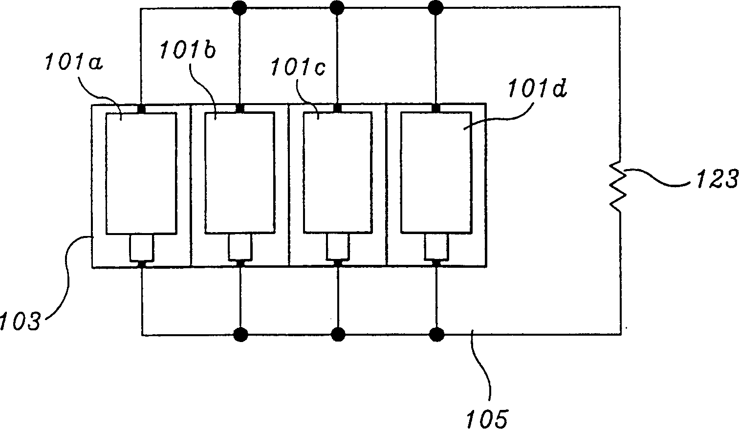
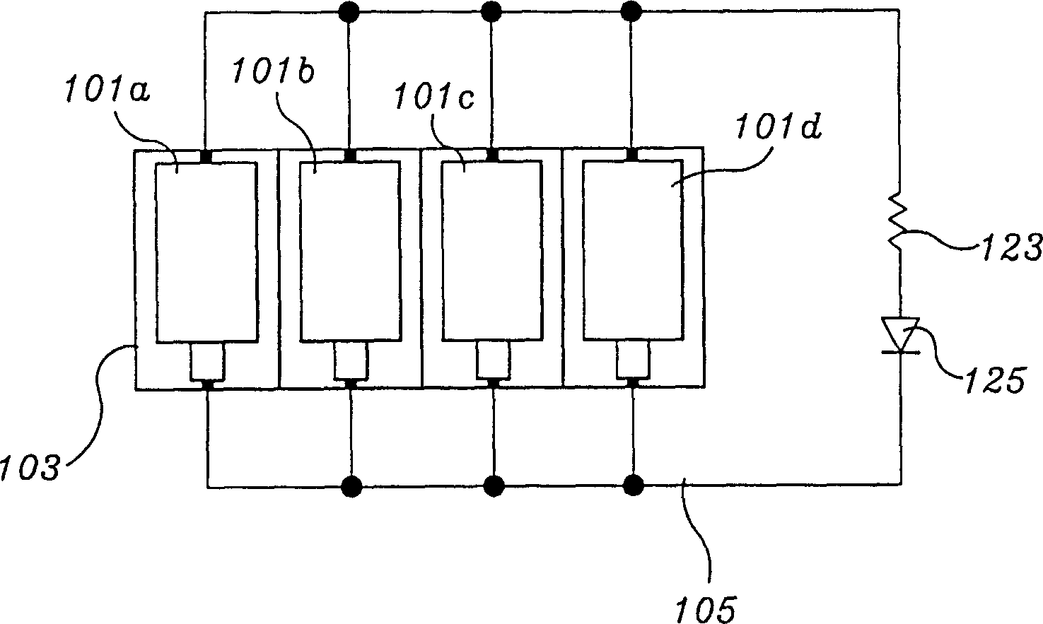
[0027] Figure 2aA controller for a rechargeable battery according to the invention is shown. The core scope of the invention shown in this figure is its control module and control method, the purpose of which is to achieve equalization of rechargeable batteries through parallel connection. What is involved in this preferred embodiment is a rechargeable battery, in other words, a backup battery comprising at least one or more battery cells as a group. Generally speaking, this kind of backup battery uses two, three, four, five, six, eight or ten battery cells in series, the purpose of which is to obtain an appropriate electromotive force for the device to accept and use. This preferred embodiment illustrates the use of four battery units 101a, 101b, 101c and 101d, which are generally used in digital cameras, camera flashes, diving flashes, and toys. In the case where at least one of the four battery cells 101a, 101b, 101c and 101d reaches the end-of-discharge voltage, the back...

Embodiment 2

[0030] The control device and control method for parallel discharge of the rechargeable batteries constituting the backup battery and the control method described in the preferred embodiment 1 are entirely for balancing before charging. What is described in this preferred embodiment is a control device for a rechargeable battery with a charging function and a control method thereof. image 3 The basic conceptual structure of a control device for controlling the rechargeable battery according to the preferred embodiment is shown.

[0031] First, there needs to be a rechargeable battery 101 comprising one or more battery cells as a set. The rechargeable battery 101 is connected to a closed loop circuit 105 comprising a switch 107 for selecting between series and parallel connection. The selection switch 107 is preferably connected to a battery condition testing device so as to select the series connection or the parallel connection according to the voltage condition of the rech...


PUM


Abstract

The present invention illustrates about the managing device for batteries which expands the durability of batteries and enhances the charging effect by maintaining the termination voltage of the rechargeable batteries used in all kinds of electrical devices and managing method for rechargeable battery thereof. The present invention provides a managing system for rechargeable batteries comprising a plurality of cells, a closed loop circuit method which connects the cells in parallel connection electrically, an electrical load means having regular voltage which is the sum of the maximum output voltage among the plurality of cells and being in parallel connection with the rechargeable cells which are connected in parallel with the closed loop circuit method, a switching means inserted between the plurality of cells and the electrical load means in order to cut off the current flowing in the electrical load means in case it reaches the discharge termination voltage of the plurality of rechargeable cells.

Description

technical field [0001] The invention relates to a control system and a control method of a rechargeable battery (or backup battery, accumulator) system. In particular, the present invention relates to control systems and methods for rechargeable batteries used in various portable electrical devices such as radiotelephones, tape recorders, cameras, torches, etc., whose terminal voltages are discharged in parallel before charging the rechargeable batteries. Balanced to extend the durability of the rechargeable battery and improve the efficiency of charging. Background technique [0002] Rechargeable batteries, also known as backup batteries or accumulators, come in a variety of shapes and sizes. According to its composition, typical rechargeable batteries are nickel cadmium (NiCd) type, lead acid type, nickel metal hydride (NiMH) type, lithium ion (Li-ion) type, lithium polymer type, alkaline type, etc. . These rechargeable batteries should be properly charged in order to h...

Claims


Application Information

Patent Timeline
IPC IPC(8): H02J7/02H01M10/44H02J7/00
CPCY02E60/12H02J7/0024H01M10/441H02J7/0063Y02E60/10H02J7/007182H01M10/448H01M10/482G01R31/3835
Inventor 吴世侊
Owner 吴世侊
Learn More