Bridge plug and bridge plug assembling method
An assembly method and bridge plug technology, applied in earthwork drilling, wellbore/well components, sealing/isolation, etc., to achieve the effects of reducing production difficulty, saving costs, and improving sealing effect
Pending Publication Date: 2022-06-10
成都托克密封件有限责任公司
View PDF0 Cites 0 Cited by
- Summary
- Abstract
- Description
- Claims
- Application Information
AI Technical Summary
Problems solved by technology
However, the strength of the rubber cylinder is low, and the general tensile strength is lower than 40MPa, so the maximum sealing limit pressure of the rubber cylinder is low, and when the temperature is too high, the sealing effect of the rubber cylinder will show a significant downward trend, and when After the temperature reaches 120°C, the sealing performance is obviously weakened
Method used
View moreImage
Smart ImageViewing Examples
Examples
Embodiment 1
Embodiment 2
Embodiment 3
Login to View More PUM
 Abstract
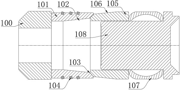
The invention discloses a bridge plug and an assembling method of the bridge plug. The bridge plug comprises a slip bowl, a slip, a cone, an expansion ring and a central pipe. The slip is arranged at one end of the slip seat; the cone is arranged at the other end of the slip; the expansion ring is sleeved on the central pipe and is arranged between the cone and the central pipe; the central pipe is connected into the cone in a screw-thread fit manner; a plurality of slip teeth are embedded in the outer wall of the slip; a first inner conical surface is formed at one end, assembled with the cone, of the slip, and a second inner conical surface is continuously formed at the inner side end of the first inner conical surface; a first outer conical surface is formed at the end, assembled with the slip, of the cone, and a second outer conical surface is continuously formed at the inner side end of the first outer conical surface; the inclination angles of the second inner conical surface and the second outer conical surface are consistent; the inclination angles of the second inner conical surface and the first outer conical surface are consistent; the inner wall of the expansion ring is of an arc-shaped structure, and the expansion ring is made of red copper. According to the scheme, the fixing effect of the slips and the sleeve is improved, cost is saved, the sealing effect of the bridge plug in a high-temperature environment is integrally improved, and high practicability is achieved.
Description
technical field [0001] The invention relates to the related technical field of structural parts for oil and gas development, in particular to a bridge plug and a method for assembling the bridge plug. Background technique [0002] Bridge plugs can temporarily block oil, gas, water and other layers, and through high-pressure fracturing operations on the upper part of the bridge plugs, oil and gas exploitation operations can be realized. [0003] The slips, as the stabilizing part of the bridge plug, interact with the casing arranged outside the bridge plug to fix the entire bridge plug, and the key components are the slip teeth arranged on the slips. Existing slips are generally installed by thermal assembly. This installation method can be used normally when the temperature of the construction environment is below 100°C, but when the temperature is greater than 100°C, due to the effect of thermal expansion, the casing will be damaged. The diameter increases, and the dimensi...
Claims
Login to View More Application Information
Patent Timeline
 Patent Type & Authority Applications(China)
IPC IPC(8): E21B33/134
CPCE21B33/134
Inventor 苏东郭明杨卿显君汪森海
Owner 成都托克密封件有限责任公司
Features
- R&D
- Intellectual Property
- Life Sciences
- Materials
- Tech Scout
- Unparalleled Data Quality
- Higher Quality Content
- 60% Fewer Hallucinations
Learn More Browse by: Latest US Patents, China's latest patents, Technical Efficacy Thesaurus, Application Domain, Technology Topic, Popular Technical Reports.
© 2025 PatSnap. All rights reserved.Legal|Privacy policy|Modern Slavery Act Transparency Statement|Sitemap|About US| Contact US: help@patsnap.com


