A drive device with a tape-receiving function and a tape-receiving method
A driving device and function technology, applied in the field of automobile testing devices, can solve the problems of large space occupation, easy to forget belts, scattered belts, etc.
- Summary
- Abstract
- Description
- Claims
- Application Information
AI Technical Summary
Problems solved by technology
Method used
Image
Examples
Embodiment 1
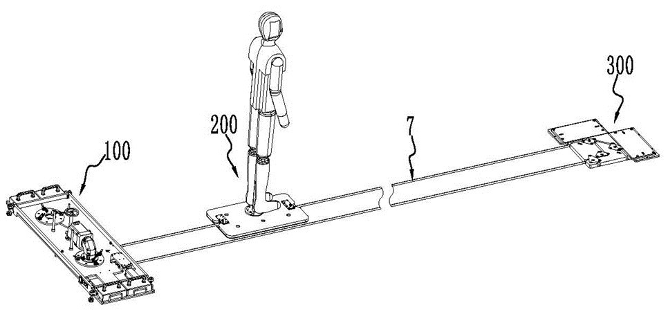
[0060] like figure 1 As shown, the driving device 100 of this embodiment is used in an AEB test system. The AEB test system mainly includes a driving device 100, a dummy target module 200 and a corner device 300. One end of the belt 7 is connected to the dummy. On the target module 200 , the other end bypasses the driving device 100 and the corner device 300 , and is also connected to the dummy target module 200 . The belt 7 is driven by the driving device 100 to drive the dummy target module 200 to move between the driving device 100 and the corner device 300 , and the car drives to the dummy target module 200 to test whether the AEB system of the car works reliably. The following describes the driving device 100 of this embodiment in detail:
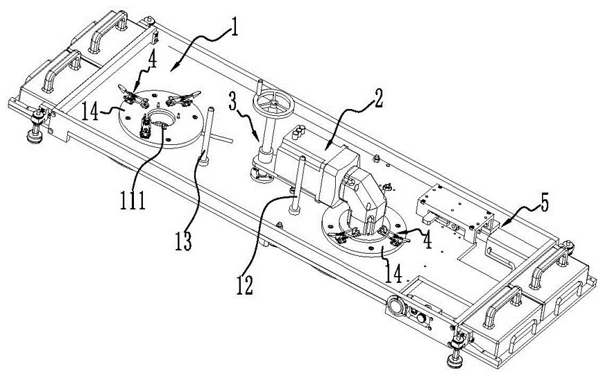
[0061] like Figure 2-Figure 5 As shown, a driving device 100 with a belt retracting function mainly includes: a mounting frame 1 , a driving motor 2 , a switching mechanism 3 , a locking mechanism 4 and a belt tensioning mechanism 5...
Embodiment 2
[0078] A tape-receiving method adopts the drive device 100 with tape-receiving function in the first embodiment, and the tape-receiving method includes the following steps:
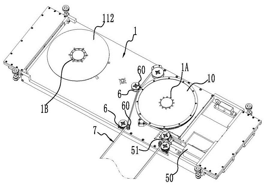
[0079] The switching mechanism 3 drives the third connecting structure 222 to separate from the first connecting structure 101, and makes the driving motor 2 switch from the first installation position 1A to the second installation position 1B, the The third connection structure 222 is connected to the second connection structure 111 . When the test of the AEB system is completed, the drive motor 2 is in the first installation position 1A, and is connected to the connection sleeve (ie, the first connection structure 101 ) at the pulley 10 . Therefore, it is necessary to separate the third connection structure 222 from the first connection structure 101 first, and then switch the position of the driving motor 2 to connect the third connection structure 222 to the second connection structure 111 .
[0080]...
PUM
 Abstract
Description
Claims
Application Information
 - R&D
- Intellectual Property
- Life Sciences
- Materials
- Tech Scout
- Unparalleled Data Quality
- Higher Quality Content
- 60% Fewer Hallucinations
Browse by: Latest US Patents, China's latest patents, Technical Efficacy Thesaurus, Application Domain, Technology Topic, Popular Technical Reports.
© 2025 PatSnap. All rights reserved.Legal|Privacy policy|Modern Slavery Act Transparency Statement|Sitemap|About US| Contact US: help@patsnap.com


