
Typical lane changing track determination method and device based on lane changing scene data and computer storage medium

A technology for scene data and determination methods, applied in computer parts, calculations, instruments, etc., can solve the problems of low extraction rate of common features of trajectories, loss of landing application of lane-changing trajectories, etc., to improve scientific rationality and high reliability. Effect

Pending Publication Date: 2022-06-17
CHINA FIRST AUTOMOBILE
View PDF0 Cites 0 Cited by
  • Summary
  • Abstract
  • Description
  • Claims
  • Application Information

AI Technical Summary

Problems solved by technology

[0004] The present invention solves the low extraction rate of common features of the trajectory existing in the existing lane-changing trajectory extraction technology and the fact that the obtained lane-changing trajectory loses its practicality when applied to automatic steering control or automatic driving due to insufficient factors considered during feature extraction. The problem of the ability of landing application

Method used


Image

  • Typical lane changing track determination method and device based on lane changing scene data and computer storage medium
  • Typical lane changing track determination method and device based on lane changing scene data and computer storage medium
  • Typical lane changing track determination method and device based on lane changing scene data and computer storage medium

Examples


Embodiment approach 1

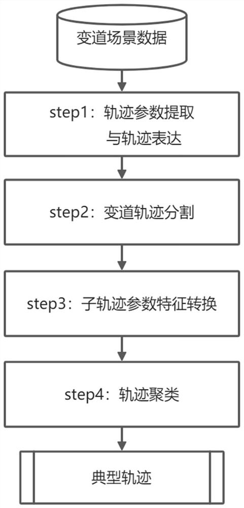
[0147] Embodiment 1. See figure 1 Illustrating this embodiment, a method for determining a typical lane change trajectory based on lane change scene data described in this embodiment includes the following steps:

[0148] The steps of trajectory parameter extraction and trajectory expression: extracting parameters representing the lane-changing trajectory based on the lane-changing scene data collected by the autonomous driving vehicle, and obtaining the trajectory expression based on the parameters;

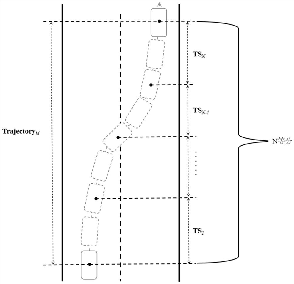
[0149] Lane change track segmentation step: divide each lane change track into N segments of N equal segments, and each segment is a sub-track;

[0150] Sub-track parameter feature conversion step: extract track parameters from each sub-track, and perform feature conversion on the track parameters to obtain the parameter features of the n-th sub-track in the m-th track:

[0151] TS' mn =[Angel' mn , Speed' mn , Position_X' mn , Position_Y m ' n ],

[0152] Among them, An...

Embodiment approach 2

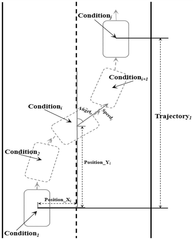
[0156] Embodiment 2. This embodiment is a further limitation of the method for determining a typical lane-change trajectory based on lane-change scene data described in Embodiment 1. In this embodiment, the parameters representing the lane-change trajectory include: steering wheel angle Angle; , vehicle speed Speed, vehicle longitudinal position Position_X, vehicle lateral position Position_Y four parameters.

[0157] This embodiment explains the lane change trajectory parameters. The lane change trajectory parameters in this embodiment take into account four parameters, see figure 2 where: the longitudinal position of the vehicle refers to the displacement of the current position of the vehicle along the lane relative to the starting time of the lane change, and the lateral position of the vehicle refers to the displacement of the current position of the vehicle perpendicular to the direction of the lane relative to the starting time of the lane change.

Embodiment approach 3

[0158] Embodiment 3. This embodiment is a further limitation of the method for determining a typical lane change trajectory based on lane change scene data described in Embodiment 1. In this embodiment, the expression based on the trajectory is: TD={TR1 , TR2, ..., TRM}, M is the total amount of all lane-change track data, TR1 represents the first lane-change track, TR2 represents the second lane-change track, ..., TRM represents The M-th lane change trajectory.

[0159] In this embodiment, the lane change trajectory is expressed as:

[0160] Trajectory = [Cond1, Cond2, ..., Condj],

[0161] Among them, j represents the end time of the lane change trajectory, and Condi represents the trajectory feature at time i

[0162] Condi=,

[0163] Where Anglei represents the steering wheel angle at time i, Speedi represents the vehicle speed at time i, Position_Xi represents the lateral position of the vehicle at time i, and Position_Yi represents the longitudinal position of the veh...


PUM


Abstract

The invention discloses a typical lane changing track determination method and device based on lane changing scene data and a computer storage medium, and relates to the technical field of automatic driving. The problems that in an existing lane changing track extraction technology, the extraction rate of track public features is low, and due to the fact that factors considered during feature extraction are insufficient, the obtained lane changing track loses the actual landing application capacity when being applied to automatic steering control or automatic driving are solved. The method comprises the following steps: extracting a parameter representing a lane changing track based on lane changing scene data collected by an automatic driving vehicle, and obtaining a track expression based on the parameter; dividing the lane changing track into a plurality of sub-tracks; converting the parameter characteristics of each sub-track, and summarizing to obtain a lane changing track data set; and clustering is carried out on the data set to obtain a typical lane changing track. The lane changing track obtained according to the actual lane changing scene is more reliable when being applied to the technical field of automatic driving.

Description

technical field [0001] The invention relates to the technical field of automatic driving, in particular to a trajectory determination technology for a lane change scene. Background technique [0002] In the field of autonomous driving technology, trajectory control and planning during vehicle driving is the key to reliable, safe and stable operation of the vehicle. Lane changing is the basic action of the vehicle driving process, and the study of typical vehicle lane changing trajectory plays an important role in the research on steering control of autonomous vehicles and the development of autonomous driving functions. [0003] At present, the existing lane-change trajectory extraction techniques generally use linear fitting and clustering methods to extract typical lane-change trajectories. Such techniques often ignore the local change information of the lane-change trajectory, and cannot effectively extract the common features of the trajectory. At the same time, the exi...

Claims


Application Information

Patent Timeline
Patent Type & Authority Applications(China)
IPC IPC(8): B60W30/18B60W60/00G06K9/62
CPCB60W30/18163B60W60/001G06F18/23213
Inventor 张建军郑建明覃斌张宇飞刘迪
Owner CHINA FIRST AUTOMOBILE
Learn More