

Neutron detector and neutron detection method
A technology of a neutron detector and a detection method, which is applied to the measurement of semiconductor detectors, the measurement of neutron radiation, instruments, etc., can solve the problems of poor time resolution and limited counting ability, and achieve high conversion efficiency and counting rate. High, low price effect
- Summary
- Abstract
- Description
- Claims
- Application Information
AI Technical Summary
Problems solved by technology
Method used
Image

Examples
Embodiment 1
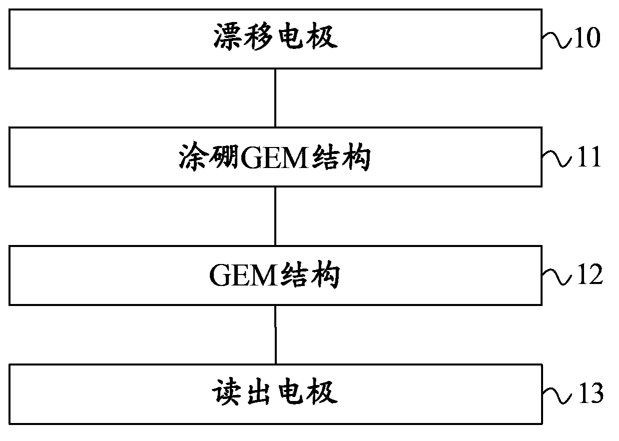
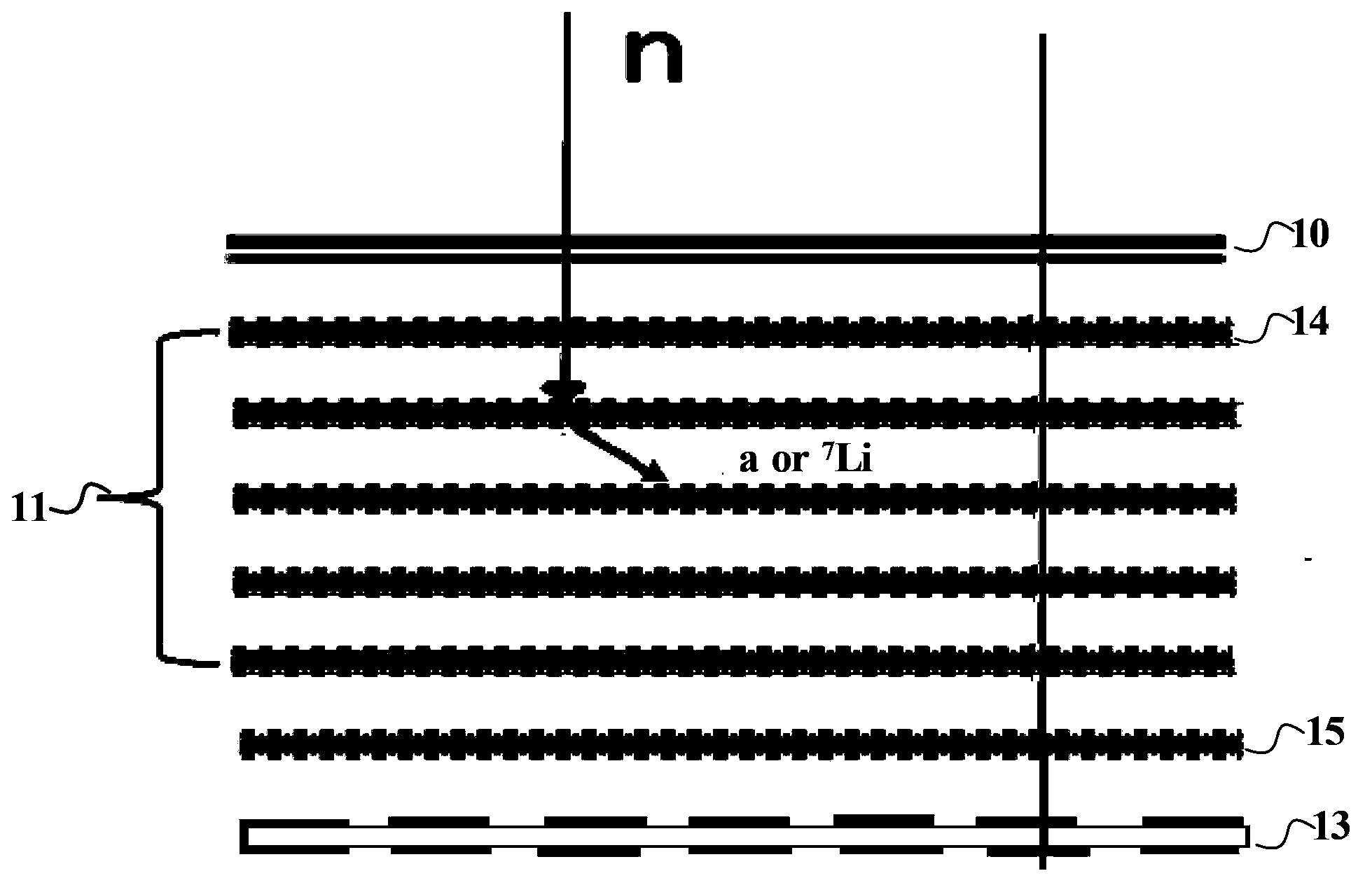
[0029] figure 1 It is a schematic structural diagram of a neutron detector provided in Embodiment 1 of the present invention. Such as figure 1 As shown, the neutron detector of this embodiment includes a drift electrode 10 for providing a drift electric field, a boron-coated GEM structure 11 for converting incident neutrons, and a primary electron for converting neutrons A GEM structure 12 for gas amplification and a readout electrode 13 for reading out gas-amplified electronic signals. The electric field between the drift electrode 10 and the boron-coated GEM structure 11 is called a drift electric field. The electric field between the GEM structure 12 and the readout electrode 13 is an ordinary electric field, which can be referred to as an electric field for short.
[0030] Such as figure 1 As shown, the drift electrode 10, the boron-coated GEM structure 11, the GEM structure 12 and the readout electrode 13 in this embodiment are arranged parallel to each other and arra...
Embodiment 2
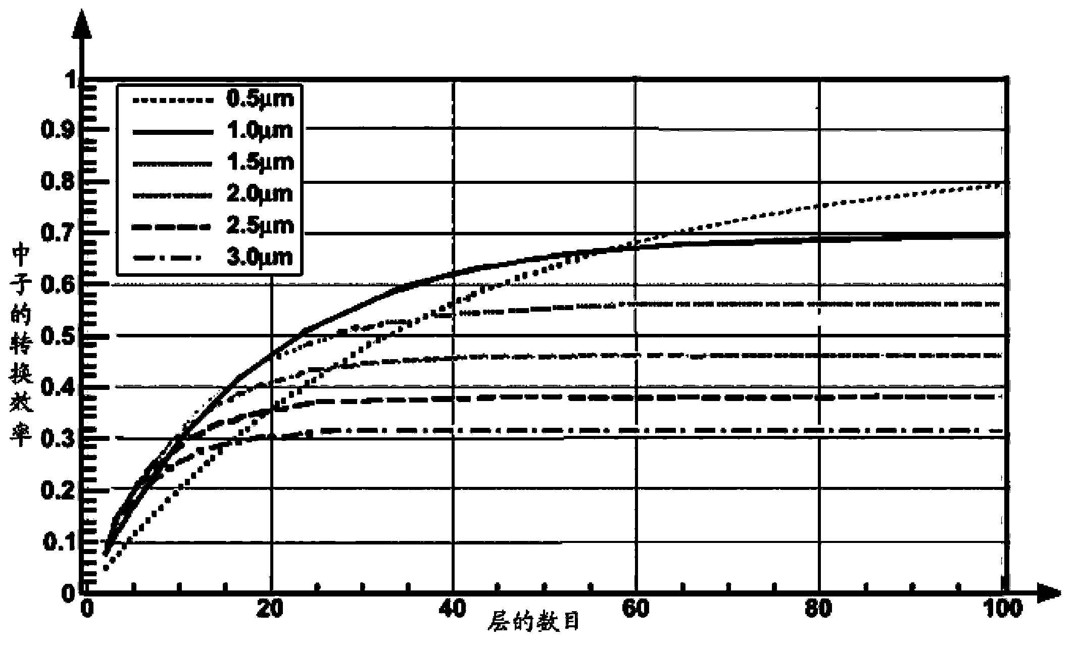
[0042] First of all, it needs to be explained that the detection efficiency is the most important performance index of neutron detectors. For the GEM-based neutron detectors in the above embodiments of the present invention, neutrons are captured by boron to produce 7 Li, α ion, has high energy (~1MeV), and the detection efficiency is basically 100%. Therefore, the neutron detection efficiency can be approximately considered as the conversion efficiency of boron to neutrons. Due to the Coulomb interaction, the pure monolayer 10 The conversion efficiency of B to thermal neutrons is at most about 5%. Such as image 3 Shown is a schematic diagram of the relationship between the neutron conversion efficiency and the number of layers in the embodiment of the present invention. Such as image 3 As shown, the intensity of the neutron beam passing through the conversion layer (that is, the first boron-coated GEM film 14) decays exponentially with the increase in thickness, so the ...
Embodiment 3
[0046] Figure 6 A schematic structural diagram of a neutron detector provided in Embodiment 3 of the present invention. On the basis of the first or second embodiment above, the neutron detector of this embodiment may also include a neutron strike position and The data processing device 16 of the hit time. The data processing device 16 is connected to the readout electrodes 13 . Such as figure 2 shown in the above figure 1 On the basis of the illustrated embodiment, the technical solution of the present invention is introduced by adding the data processing device 16 as an example. Wherein the data processing device 16 may also use existing related hardware to integrate and implement its functions. Specifically, the neutron detection principle of the neutron detector of this embodiment is the same as that of the above-mentioned embodiment, and details can be referred to the description of the above-mentioned embodiment, which will not be repeated here.
[0047] The dete...
PUM
| Property | Measurement | Unit |
|---|---|---|
| Thickness | aaaaa | aaaaa |
Abstract
Description
Claims
Application Information