An IoT-based edge box

An Internet of Things and edge technology, applied in the direction of cooling/ventilation/heating transformation, alarms, instruments, etc., can solve problems such as poor hardware heat dissipation, and achieve the effect of increasing retention time and heat dissipation effect

Active Publication Date: 2022-07-22
SICHUAN SANSIDE TECH CO LTD
View PDF12 Cites 0 Cited by
  • Summary
  • Abstract
  • Description
  • Claims
  • Application Information

AI Technical Summary

Problems solved by technology

[0004] The purpose of the present invention is to provide an edge box based on the Internet of Things to solve the problem of poor heat dissipation of highly integrated hardware in the edge box in the prior art

Method used


Image

  • An IoT-based edge box
  • An IoT-based edge box

Examples


Embodiment 1

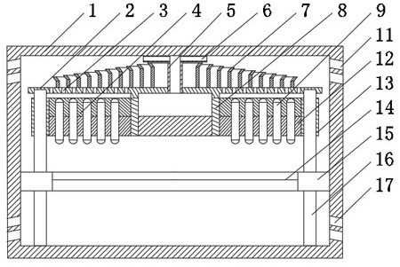
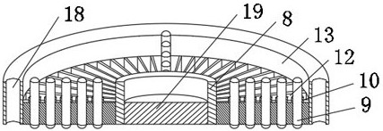
[0025] like figure 1 and figure 2 As shown, this embodiment includes a casing 1, a hardware circuit board 14 is arranged inside the casing 1, an interface module electrically connected to the hardware circuit board 14 is arranged on the outer wall of the casing 1, and a heat dissipation device is arranged above the hardware circuit board 14 The heat dissipation system includes a coaxial inner ring body 8 and an outer ring body 13, a plurality of primary fins 12 are provided on the outer circumferential wall of the inner ring body 8 along the radial direction of the inner ring body 8, and the inner ring body 8 passes through the primary fins. The sheet 12 is connected to the outer ring body 13, and a plurality of heat pipes 9 are arranged at intervals between the side walls of the two adjacent primary fins 12, and copper pillars 19 are fixed inside the inner ring body 8; The bottom plate 2 on the upper end face of the body 13, a plurality of overflow holes 3 are opened on the...

Embodiment 2

[0032] like figure 1 and figure 2 As shown, on the basis of Embodiment 1, this embodiment further defines the diversion fins that play a secondary heat dissipation function.

[0033] That is, in this embodiment, the axial lengths of the plurality of the drainage fins are set to decrease from the inside to the outside along the radial direction of the inner ring body 8 . The heat located at the periphery of the hardware circuit board 14 passes through the primary fins 12 after mixing with the air, and then enters the annular diversion fins after passing through the overflow holes 3. The axial lengths of the plurality of diversion fins are along the inner ring body. The radial direction of 8 decreases from the inside to the outside, so that a plurality of hot air flow conduction channels with decreasing heights can be formed above the bottom plate 2, so that the heat carried by the hot air when it moves up in the drainage fins of different heights has a decaying trend. That i...

Embodiment 3

[0040] like figure 1 and figure 2 As shown, on the basis of Embodiment 1, this embodiment also includes a plurality of positioning cylinders 10 arranged in the filling layer 4 and matched with the heat pipes 9, and the lower end surfaces of the positioning cylinders 10 are fixed on two adjacent places. On the upper end of the primary fin 12, the middle part of the heat pipe 9 is expanded to the positioning cylinder 10; At least two positioning holes 18 are formed on the lower end surface of the casing 1 . The bottom of the casing 1 is provided with a guide post 16 . The hardware circuit board 14 is connected to the inner wall of the housing 1 through the heat insulating plate 15, so that the heat generated by each component due to work will not be directly conducted to the housing 1, and the heat insulating plate 15, the inner ring body are sequentially connected to the heat insulating plate 15 and the inner ring body through the guide post 16. 8 and the bottom plate 2 are ...


PUM


Abstract

The invention relates to the technical field of edge computing technology, and discloses an edge box based on the Internet of Things. A hardware circuit board is arranged inside the casing, and a plurality of primary fins are arranged on the outer circumferential wall along the radial direction of the inner ring body. The inner ring body is connected with the outer ring body through primary fins, and a plurality of heat pipes are arranged between the side walls of two adjacent primary fins, and copper columns are fixed inside the inner ring body; Flow holes, a plurality of drainage fins are arranged on the bottom plate at intervals, a guide pipe is arranged in the middle of the bottom plate, a plurality of shunt pipes are connected to the upper end of the guide pipe, and a plurality of exhaust holes are opened in the upper section of the outer wall of the shell, and in the lower section of the outer wall of the shell There are multiple air intake holes. The present invention adopts a fanless heat dissipation structure, performs the heat dissipation process on the components on the hardware circuit board in real time, and utilizes the differential pressure inside the edge box to continuously introduce air while rapidly expelling heat to ensure that the elements inside the edge box are normal operation of the device.

Description

technical field [0001] The invention relates to the technical field of edge computing, and relates to an edge box based on the Internet of Things. Background technique [0002] As the construction of smart cities is in full swing, there are more and more application requirements for edge computing. Traditional cloud computing has been unable to meet the application computing in many scenarios today, and edge computing that reduces terminal delay has emerged as the times require. The edge box is an AI solution that integrates hardware devices, software management systems and algorithm models for edge computing scenarios. The edge box is lightweight and can be flexibly deployed on-site by placing it, wall-mounted installation, etc., and can better adapt to the on-site deployment environment. [0003] The software management system is mainly used to manage the parameters and settings of the system, combining hardware equipment, algorithm models, and scene requirements to reali...

Claims


Application Information

Patent Timeline
Patent Type & Authority Patents(China)
IPC IPC(8): H04Q1/02G08B19/00H05K7/20
CPCH04Q1/035G08B19/00H05K7/20418H05K7/20336H05K7/20127
Inventor 张秀才薛方俊李志刚
Owner SICHUAN SANSIDE TECH CO LTD
Why Eureka
Try Eureka