Automobile transmission shaft polishing device based on intelligent automobile manufacturing

A technology of intelligent manufacturing and transmission shaft, applied in grinding/polishing safety devices, manufacturing tools, grinding machines, etc., can solve the problems of unstable clamping, increase structure, etc., to increase the transmission effect and prevent the effect of jamming

Pending Publication Date: 2022-06-21
邵彭伟
1 Cites 1 Cited by

AI-Extracted Technical Summary

Problems solved by technology

[0002] Existing grinding devices for automobile transmission shafts, such as a high-efficiency grinding device for processing automobile transmission shafts with a dust removal function disclosed in Patent No. CN202120582736. The part supports the bottom end of the...

Method used

[0027] Based on the foregoing embodiments, the technical problem that the application intends to solve is how to facilitate strengthening the effect of stabilizing the drive shaft. For this reason, as shown in Fig. 1 to Fig. 15, the present application is provided with the first chute 5 on the workbench 1, and on the first chute 5, the mounting frame 6 that is slidably connected with it is set, so that it can be adjusted by adjusting two The position of the placement frame 6 facilitates the placement of transmission shafts of different lengths to prevent the gravity at both ends of the transmission shaft from tilting, and at the same time, the transmission shaft is placed through the placement groove 6a and the phenomenon of the transmission shaft sliding out due to inertia is reduced through the support rod 6a1, so that the first A sliding block 7 is affected by gravity so as to overcome the elastic force of the first elastic member 8 so that the first sliding block 7 moves downward through the first guide rail 6b and the first sliding rod 7a, because the bottom end of the firm jaw 9 is in contact with the first sliding block 7 Hinged and a first connecting rod 9a connected to the placement frame 6 is pierced in the middle, and the stable jaw 9 is hinged with the first connecting rod 9a, thereby forming a lever, which drives the connection and fixes the first sliding block 7 when it descends The jaws 2 move toward the position of the placement groove 6a to hold the transmission shaft on it firmly, and the second linear driver will drive the grinding roller shaft 4 to move down to press the transmission shaft first and then perform the grinding process, while pressing and grinding Between the first linear driver 3 will drive two fixed jaws 2 to clamp the left and right ends of the transmission shaft, and when the transmission shaft is placed, the elastic force of the first elastic member 8 will overcome the gravity of the first sliding block 7 to make it Through the upward movement of the first guide rail 6b and the first sliding rod 7a, the two fixed jaws 2 are located away from the placement groove 6a and coincide with the support rod 6a1. It should be noted that after the transmission shaft is placed, the second linear drive is placed, and a mechanical arm needs to be installed at one end of the workbench 1 to facilitate loading and unloading. The mechanical arm is not shown in the figure.
[0033] Based on the above-mentioned embodiments, the technical problem that the application intends to solve is how to facilitate the effect of different gravity at both ends of the transmission shaft to affect the placement effect. For this reason, as shown in Figure 5 to Figure 7, the application facilitates the movement of the placement frame 6 through the second guide rail 6c5, and then drives the two threaded rods 6c7 to rotate throu...

Abstract

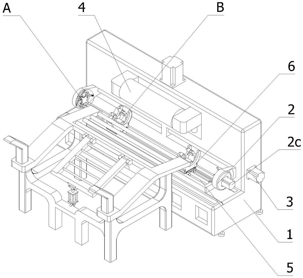
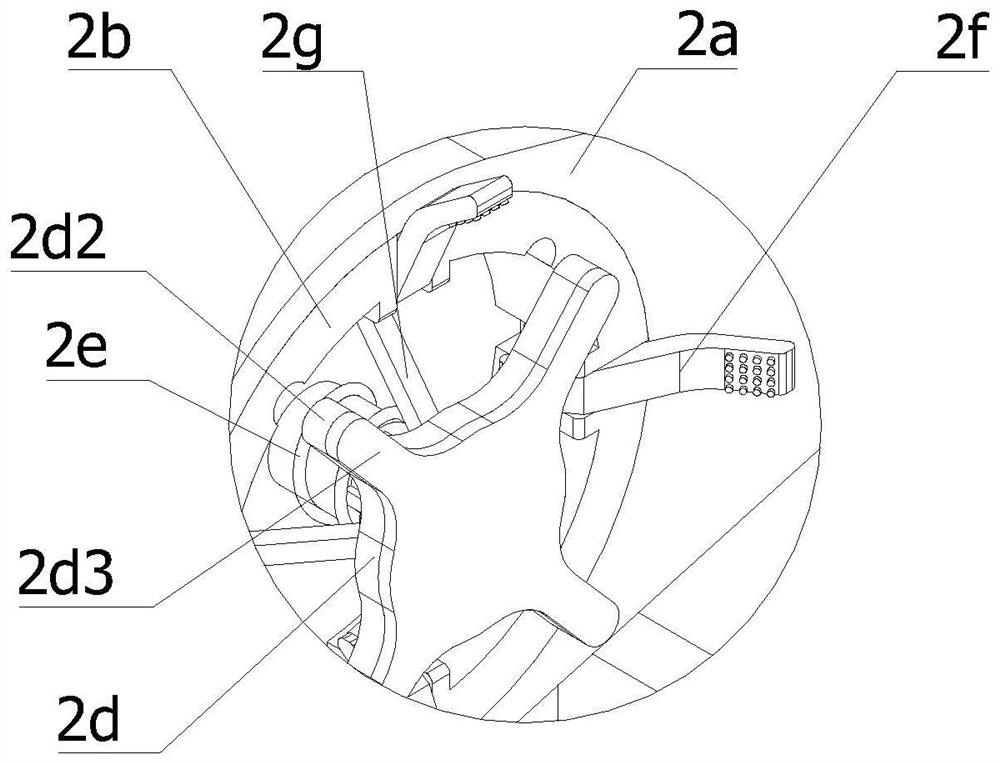
The invention relates to the technical field of automobile transmission shaft machining, in particular to an automobile transmission shaft polishing device based on intelligent automobile manufacturing, which comprises a worktable, two fixed clamping jaws, a first linear driver, a polishing roll shaft and a second linear driver, a stabilizing assembly is arranged on the workbench and comprises a first sliding groove, a placing frame, a first sliding block, a first elastic piece and a stabilizing clamping jaw. Transmission shafts with different lengths can be conveniently placed by adjusting the position of a placing frame through a first sliding groove and the placing frame, meanwhile, the situation that the transmission shafts slide out due to inertia is reduced through a supporting rod, and a first sliding block is influenced by the gravity of the transmission shafts, so that the elastic force of a first elastic piece is overcome, and the first sliding block moves downwards; the bottom end of the stable clamping jaw is hinged to the first sliding block, and the first connecting rod in the middle of the stable clamping jaw is hinged to the placing frame, so that a lever is formed, and the first sliding block drives the fixed clamping jaw to move when descending so as to stably clamp the transmission shaft on the fixed clamping jaw.

Application Domain

Technology Topic

Image

  • Automobile transmission shaft polishing device based on intelligent automobile manufacturing
  • Automobile transmission shaft polishing device based on intelligent automobile manufacturing
  • Automobile transmission shaft polishing device based on intelligent automobile manufacturing

Examples

  • Experimental program(1)

Example Embodiment

[0051] In order to further understand the features, technical means, and specific goals and functions of the present invention, the present invention will be described in further detail below with reference to the accompanying drawings and specific embodiments.
[0052] like Figure 1 to Figure 15 As shown, this application provides:
[0053] An automobile transmission shaft grinding device based on automobile intelligent manufacturing, comprising a worktable 1, two fixed jaws 2, a first linear drive 3, a grinding roller shaft 4 and a second linear drive; The assembly includes a first chute 5, a mounting rack 6, a first sliding block 7, a first elastic member 8 and a stable clamping jaw 9. The first chute 5 is arranged on the workbench 1; the mounting rack 6 is provided with at least two and The two placement racks 6 are evenly distributed on the first chute 5, the placement rack 6 is slidably connected to the first chute 5, and the middle part of the placement rack 6 is provided with a semicircular placement slot 6a, and the left and right sides of the placement slot 6a are set. An arc-shaped support rod 6a1 is formed on the side, and the bottom end of the placement groove 6a is also provided with a downwardly concave first guide rail 6b, and a plurality of first guide rails 6b are provided; The sliding block 7 is provided with the first sliding rods 7a with the same number as the first guide rails 6b and one-to-one correspondence; Two ends of an elastic member 8 are respectively connected to the mounting frame 6 and the first sliding block 7; two stable clamping jaws 9 are provided and are evenly distributed on the left and right ends of the first sliding block 7, and the two stable clamping jaws 9 are arcs. and the bottom ends of the two fixed jaws 2 are hinged with the left and right ends of the first sliding block 7 respectively, and the middle part of each stable jaw 9 is also provided with a first connecting rod 9a connected with the mounting frame 6, The stabilizing jaw 9 is hinged with the first connecting rod 9a.
[0054] Based on the above embodiments, the technical problem to be solved by the present application is how to facilitate the enhancement of the effect of stabilizing the transmission shaft. For this, as Figure 1 to Figure 15 As shown, in the present application, a first chute 5 is provided on the workbench 1, and a mounting rack 6 that is slidably connected to the first chute 5 is provided on the first chute 5, so that the positions of the two mounting racks 6 can be adjusted so as to facilitate different The length of the transmission shaft is placed to prevent the inclination caused by the even gravity at both ends of the transmission shaft. At the same time, the transmission shaft is placed through the placement groove 6a and the support rod 6a1 is used to reduce the phenomenon that the transmission shaft is slipped out by inertia, so that the first sliding block 7 is affected by gravity to overcome The elastic force of the first elastic member 8 makes the first sliding block 7 move downward through the first guide rail 6b and the first sliding rod 7a, because the bottom end of the stable clamping jaw 9 is hinged with the first sliding block 7 and there is a The first connecting rod 9a connected to the mounting frame 6 is placed, and the stable clamping claw 9 is hinged with the first connecting rod 9a, thereby forming a lever, so that when the first sliding block 7 is lowered, it drives the connecting fixed clamping claw 2 toward the position of the mounting groove 6a. Move the drive shaft on it to hold it firmly, the second linear drive will drive the grinding roller shaft 4 to move down to press the drive shaft before grinding, and the first linear drive 3 will move between pressing and grinding. The two fixed jaws 2 are driven to clamp the left and right ends of the transmission shaft. At the same time, when the transmission shaft is placed, the elastic force of the first elastic member 8 will overcome the gravity of the first sliding block 7 and make it pass through the first guide rail 6b and the first sliding rod. 7a is moved upward so that the two fixed jaws 2 are located away from the seating groove 6a and coincide with the support rod 6a1. It should be noted that the second linear drive is placed after the transmission shaft is placed, and a mechanical arm needs to be provided at one end of the worktable 1 to facilitate loading and unloading. The robotic arm is not shown in the diagram.
[0055] further:
[0056] The first sliding slot 5 is provided with a second sliding rod 5a, the bottom end of each mounting frame 6 is provided with a second sliding block 6c corresponding to the second sliding rod 5a, and the bottom end of each second sliding block 6c is provided with a corresponding sliding block 6c. The hinged oblique rods 6c1, the bottom ends of the two oblique rods 6c1 are provided with a third linear actuator 6c2 and a connecting block 6c3 hinged with the two oblique rods 6c1 respectively, and the output end of the third linear actuator 6c2 is arranged vertically upward and connected with the Block 6c3 is connected.
[0057] Based on the above-mentioned embodiments, the technical problem to be solved by the present application is how to facilitate the phenomenon that the two mounting racks 6 can be synchronously approached or separated. For this, as Figures 13 to 15 As shown, in the present application, the third linear drive 6c2 drives the connecting block 6c3 to move up or down, thereby driving the connecting block 6c3 to move up and down so as to stretch the oblique rod 6c1 for adjustment, so that the second sliding block 6c moves along the second sliding rod 5a. Moving, the hinged connection of the oblique rod 6c1 with the connecting block 6c3 and the second sliding block 6c is to increase the transmission effect and prevent clamping. It should be noted that the oblique rod 6c1 is inclined for easy transmission, and the first linear drive 3 To increase the synchronization of both ends The motion effect can also be of similar structure.
[0058] further:
[0059] A plurality of first guide posts 1a extending downward are provided on the worktable 1 above the connection block 6c3, and the connection block 6c3 is provided with first guide sleeves 6c4 corresponding to the same number as the first guide posts 1a.
[0060] Based on the above-mentioned embodiments, the technical problem to be solved by the present application is how to stabilize the sliding up and down of the connecting block 6c3. For this, as Figures 13 to 15 As shown, in the present application, a first guide post 1a extending downward is provided above the connection block 6c3 on the workbench 1, and a first guide sleeve 6c4 corresponding to the first guide post 1a is provided on the connection block 6c3 for stable connection. The transmission of the block 6c3 prevents its inclination from affecting the synchronous movement of the two racks 6 .
[0061] further:
[0062] The second sliding block 6c is provided with a second guide rail 6c5, the left and right ends of the second guide rail 6c5 are provided with a second sliding groove 6c6, and a threaded rod 6c7 is provided inside the second sliding groove 6c6, and one end of the two threaded rods 6c7 Both are arranged on the outer side of the second sliding block 6c, and one end of the two threaded rods 6c7 located on the outer side of the second sliding block 6c is provided with a timing belt connecting the two threaded rods 6c7, and the two threaded rods 6c7 are located on the outer side of the second sliding block 6c. One end is provided with a knob in the shape of a hexagonal column, the mounting frame 6 is provided with a moving block 6d corresponding to the second guide rail 6c5, and the moving block 6d is provided with a third sliding groove corresponding to the second chute 6c6 and the threaded rod 6c7 Block 6d1.
[0063] Based on the above embodiments, the technical problem to be solved by the present application is how to facilitate the placement effect due to the different gravitational forces at both ends of the transmission shaft. For this, as Figure 5 to Figure 7 As shown, the present application facilitates the movement of the placement rack 6 through the second guide rail 6c5, and then drives the two threaded rods 6c7 to rotate by rotating the knob through the synchronous belt, so that the third sliding block 6d1 moves along the second chute 6c6 to adjust the placement rack The position of 6 is placed in the position of 6. Different gravity at both ends of the rotating shaft affects the placement. The knob is in the shape of a hexagonal prism to facilitate the adjustment effect through a wrench. The second guide rail 6c5 and the moving block 6d corresponding to the second guide rail 6c5 are to strengthen the support effect. It should be noted that one end of the second sliding block 6c is detachable for easy maintenance.
[0064] further:
[0065] The first sliding block 7 is provided with two evenly distributed first concave portions 7b, and each first concave portion 7b is provided with a first rotating roller 7b1, and a second roller shaft 7b1 is provided in the middle portion of the stabilizing jaw 9 to the top. The recessed portion 7c and the second recessed portion 7c are provided with a plurality of uniformly distributed second rotating roller shafts 7c1.
[0066] Based on the above embodiments, the technical problem to be solved by the present application is how to facilitate the rotation of the transmission shaft during grinding. For this, as image 3 , Figure 5 and Image 6 As shown, the present application installs the first rotating roller shaft 7b1 and the second rotating roller shaft 7c1 by arranging the first concave portion 7b and the second concave portion 7c, so as to facilitate the rotation of the transmission shaft, and the second rotating roller shaft 7c1 is provided with a plurality of It is convenient for the transmission shaft to be clamped by the stable clamping jaw 9 so that at least one second rotating roller shaft 7c1 can be connected with it for transmission.
[0067] further:
[0068] The fixed jaw 2 includes a first bracket 2a, abutting plate 2b, a first motor 2c, a pushing plate 2d, a second elastic member 2e, a clamping plate 2f and a transmission rod 2g. The first bracket 2a is provided on the workbench 1 And connected with the first linear driver 3; the abutting plate 2b is circular and is arranged on the first bracket 2a, the abutting plate 2b is rotatably connected with the first bracket 2a, and a plurality of evenly distributed The first hinge port 2b1; the first motor 2c is arranged on the first bracket 2a and connected with the abutting plate 2b; the pushing plate 2d and the abutting plate 2b are coaxially arranged on one side of the abutting plate 2b, and the pushing plate 2d The back is provided with a second hinge port 2d1 with the same number as the first hinge port 2b1 and one-to-one correspondence; the second elastic member 2e is provided between the abutting plate 2b and the pushing plate 2d; the clamping plate 2f and the first hinge port The number of 2b1 is the same and corresponds to one-to-one, the middle part of the clamping plate 2f is rotatably connected with the first hinge port 2b1 and one end is located between the abutting plate 2b and the pushing plate 2d; one end of the transmission rod 2g is rotatably connected with the second hinge port 2d1 , the other end of the transmission rod 2g is hinged with one end of the clamping plate 2f located between the abutting plate 2b and the pushing plate 2d, and the clamping plate 2f is in an inclined state.
[0069] Based on the above embodiments, the technical problem to be solved by the present application is how to easily clamp the left and right ends of the transmission shaft. For this, as Figure 8 to Figure 11As shown, in the present application, the first bracket 2a is connected to the first linear actuator 3 so that it drives the clamping plate 2f to move, so that the clamping plate 2f first abuts against the transmission shaft to overcome the elastic force of the second elastic member 2e to drive the clamping plate 2f. The displacement of the pushing plate 2d drives the transmission rod 2g to move, and pushes the bottom end of the clamping plate 2f to move away from the axis of the abutting plate 2b, so that the front end of the clamping plate 2f clamps the peripheral wall of the transmission shaft, and then passes through the first The motor 2c drives the abutment plate 2b, the clamping plate 2f, etc. to grind the rotating parts. It should be noted that only one fixed jaw 2 is provided with the first motor 2c to prevent the different speeds of the motors at both ends from affecting the grinding. The line driver 3 drives the first bracket 2a to disengage the pushing plate 2d from the transmission shaft and the second elastic member 2e makes the pushing plate 2d and the clamping plate 2f reset.
[0070] further:
[0071] A push rod 2d2 is disposed on the push plate 2d between the two second hinge ports 2d1. The push rod 2d2 and the clamping plate 2f are both sleeved with a buffer pad 2d3 made of rubber material on one side.
[0072] Based on the above embodiments, the technical problem to be solved by the present application is how to enhance the gripping effect on the transmission shaft. For this, as figure 2 As shown, in the present application, the contact area of ​​the pushing plate 2d is increased by pushing the rod 2d2 to prevent it from being inserted into the hollow structure of part of the drive shaft, and it is displaced from the pushing plate 2d to prevent it from affecting the clamping of the clamping plate 2f, and Both the push rod 2d2 and the clamping plate 2f are sleeved with a buffer pad 2d3 made of rubber material on one side. First, is it to perform a buffering effect to prevent it from damaging the drive shaft, and second, it is convenient to strengthen the friction between the drive roller shaft It is easy to drive it to rotate together.
[0073] further:
[0074] The abutting plate 2b is provided with a second guide sleeve 2b2 extending toward the push plate 2d, and the push plate 2d is provided with a second guide post 2d4 corresponding to the second guide sleeve 2b2.
[0075] Based on the above embodiments, the technical problem to be solved by the present application is how to prevent the inclination of the pushing plate 2d from affecting the clamping of the clamping plate 2f. For this, as Figure 8 to Figure 11 As shown, in the present application, the second guide post 2d4 and the second guide sleeve 2b2 are provided to enhance the transmission effect of the pushing plate 2d to prevent it from tilting.
[0076] further:
[0077] The second guide post 2d4 is provided with a plurality of evenly distributed limit blocks 2d5, and the second guide sleeve 2b2 is provided with limit grooves 2b3 corresponding to the limit blocks 2d5 in one-to-one quantity.
[0078] Based on the above embodiments, the technical problem to be solved by the present application is how to prevent the pushing plate 2d and the abutting plate 2b from moving relative to each other so that the pushing rod 2d2 affects the clamping of the clamping jaws. For this, as Figure 9 As shown, in the present application, a limiting block 2d5 is provided on the second guide post 2d4 and a second limiting groove 2b3 is provided on the second guide sleeve 2b2 to enhance the frictional force to prevent the two from rotating relative to each other.
[0079] further:
[0080] The bottom end of the first sliding rod 7a is provided with a circular top cover 7a1, and the radius of the circle where the top cover 7a1 is located is larger than the radius of the circle where the first sliding rod 7a is located. Protrusion 6b1.
[0081] Based on the above embodiments, the technical problem to be solved by the present application is how to prevent the first sliding block 7 from being separated from the mounting frame 6 by the elastic force of the first elastic member 8 . For this, as Figure 7 As shown, in the present application, a top cover 7a1 is provided at the bottom end of the first sliding rod 7a, and the radius of the circle where the top cover 7a1 is located is larger than the radius of the circle where the first sliding rod 7a is located, so as to be consistent with the raised portion 6b1 provided on the first guide rail 6b. In order to prevent it from disengaging, it should be noted that an abutment block needs to be provided on the second linear actuator, so that the pressed rotating shaft makes the top cover 7a1 abut against the bottom end of the first guide rail 6b to enhance the stabilization effect.
[0082] The above examples only represent one or several embodiments of the present invention, and the descriptions thereof are specific and detailed, but should not be construed as a limitation on the scope of the patent of the present invention. It should be pointed out that for those of ordinary skill in the art, without departing from the concept of the present invention, several modifications and improvements can also be made, which all belong to the protection scope of the present invention. Therefore, the protection scope of the patent of the present invention should be subject to the appended claims.

PUM

no PUM

Description & Claims & Application Information

We can also present the details of the Description, Claims and Application information to help users get a comprehensive understanding of the technical details of the patent, such as background art, summary of invention, brief description of drawings, description of embodiments, and other original content. On the other hand, users can also determine the specific scope of protection of the technology through the list of claims; as well as understand the changes in the life cycle of the technology with the presentation of the patent timeline. Login to view more.

Similar technology patents

Urethral dilator with core

PendingCN112843442AAvoid Catheter DifficultyImprove transmission effectSurgeryDilatorsUrethral dilatorsUrethral Catheters
Owner:李宁

Intelligent fire-fighting internet-of-things transmission equipment

PendingCN111935953AImprove transmission effectImprove cooling effectCasings/cabinets/drawers detailsAlarmsEmbedded systemTransmission equipment
Owner:江西远大科技有限公司

Method and device for modulating and adjusting sending terminal and sending terminal

ActiveCN103155466AImprove accuracyImprove transmission effectChannel coding adaptationTransmission rate adaptationSignal-to-noise ratio (imaging)Signal-to-quantization-noise ratio
Owner:HUAWEI TECH CO LTD

Reflective light-transmitting band and method for laser LD light source

InactiveCN102889552AGood energy saving effectImprove transmission effectLighting device detailsFluorescenceEngineering
Owner:TIANJIN TIANXING ELECTRONICS +3

Classification and recommendation of technical efficacy words

  • Improve transmission effect
  • Avoid jamming

Remote operation processing method and device

ActiveCN111158577AImprove transmission effectImprove the input experience effectInput/output processes for data processingData transmissionTele operation
Owner:BEIJING QIANXIN TECH +1

Anti-corrosion cable material based on epoxy resin and preparation method thereof

InactiveCN108485049AIdeal anti-corrosion functionImprove transmission effectPlastic/resin/waxes insulatorsChemistryDioxide titanium
Owner:合肥市闵葵电力工程有限公司

A superconducting cable

Owner:新宇电缆集团股份有限公司

Inverting thrombectomy apparatuses and methods

ActiveUS20170348014A1Avoid jammingEasily formedTractorMechanical thrombectomy
Owner:STRYKER CORP
Why Eureka
Try Eureka