Horse head assembly for pumping unit
An oil pumping unit and donkey head technology, which is applied in the field of oil field operation devices, can solve the problems of inconvenient wire rope movement, damage to the connection stability of the donkey head and the beam, the beam and the support frame, etc., and achieve the effect of easy adjustment.
Inactive Publication Date: 2022-06-21
东营高航技术有限公司
View PDF0 Cites 0 Cited by
- Summary
- Abstract
- Description
- Claims
- Application Information
AI Technical Summary
Problems solved by technology
It can be seen from the above setting method that in the prior art, the head of the donkey is biased to one side of the beam, so that the side of the beam bears a larger tensile force, which will damage the connection stability between the head of the donkey and the beam, and the connection between the beam and the supporting frame.
Method used
View moreImage
Smart ImageViewing Examples
Examples
Embodiment Construction
Login to View More PUM
 Abstract
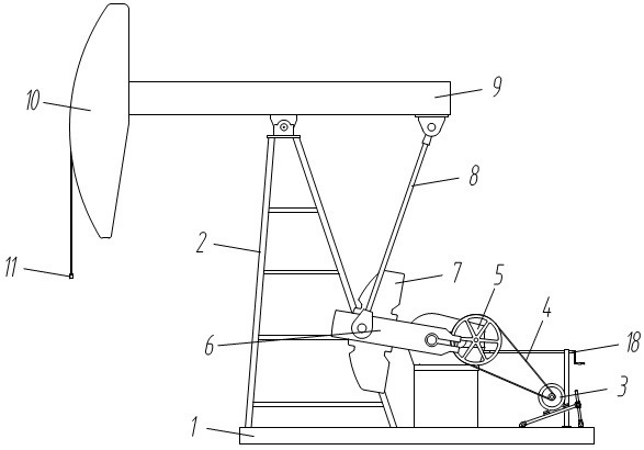
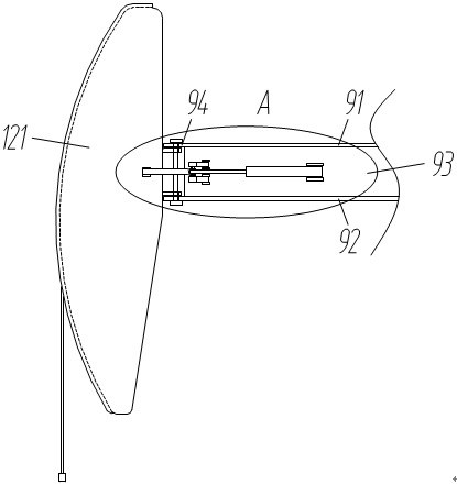
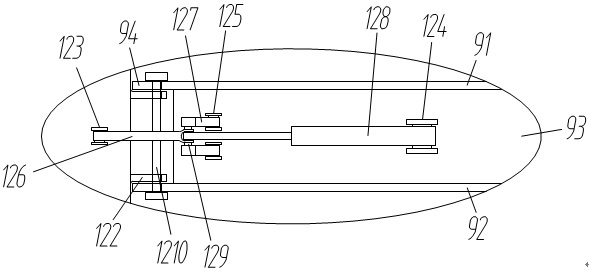
The invention belongs to the technical field of petroleum field operation devices, and provides a horse head assembly for a pumping unit which is provided with a base, a supporting frame, a driving motor and a reduction gearbox are fixed to the base, the driving motor is connected with the reduction gearbox through a belt, an output shaft of the reduction gearbox is connected with a crank, a balance block is arranged on the crank, and a connecting rod is hinged to the crank. The connecting rod is hinged to one end of the walking beam, the walking beam is rotatably supported on the supporting frame, the horse head is fixed to the other end of the walking beam, the beam hanger is connected to the lower portion of the horse head, the walking beam is provided with a top plate, a bottom plate and two side plates, the side plates are symmetrically arranged between the top plate and the bottom plate, the side plates are welded to the top plate and the bottom plate respectively, and a connecting base is formed at one end of the walking beam. The connecting base is used for hinging a horse head. Compared with the prior art, the device has the following beneficial effects that when an oil well needs to be maintained, the horse head located above the oil well is rotationally moved away, and meanwhile the problem that in the prior art, the horse head deflects towards one side, and consequently a walking beam is twisted can be solved.
Description
technical field [0001] The invention belongs to the technical field of oilfield operation devices, and belongs to a tool for a pumping unit, in particular to a donkey head assembly for a pumping unit. Background technique [0002] Beam pumping unit is the type of pumping unit with the largest number of applications and the widest distribution in oil fields. The main structure includes: The donkey head of the oil machine is welded by steel plates, and is matched with the forearm of the beam through the donkey head pin. [0003] There are three ways of connecting the donkey head and the beam in the prior art: a rotating shaft type donkey head side turning mechanism, a dismountable donkey head side turning mechanism, and a donkey head side turning mechanism with three pin shafts. It can be seen from the above arrangement that in the prior art, the head of the donkey is biased to one side of the beam, so that the tension on one side of the beam is relatively large, which will d...
Claims
Login to View More Application Information
Patent Timeline
 Patent Type & Authority Applications(China)
IPC IPC(8): E21B43/00
CPCE21B43/00
Inventor 崔明涛成涛
Owner 东营高航技术有限公司
Features
- R&D
- Intellectual Property
- Life Sciences
- Materials
- Tech Scout
- Unparalleled Data Quality
- Higher Quality Content
- 60% Fewer Hallucinations
Learn More Browse by: Latest US Patents, China's latest patents, Technical Efficacy Thesaurus, Application Domain, Technology Topic, Popular Technical Reports.
© 2025 PatSnap. All rights reserved.Legal|Privacy policy|Modern Slavery Act Transparency Statement|Sitemap|About US| Contact US: help@patsnap.com


