
Coaxial fluid liquid path structure

A fluid and liquid circuit technology, applied in the field of coaxial fluid liquid circuit structure, can solve the problem of poor coaxial co-flow effect and achieve the effect of convenient analysis and identification

Pending Publication Date: 2022-06-21
MEDCAPTAIN MEDICAL TECH
View PDF4 Cites 0 Cited by
  • Summary
  • Abstract
  • Description
  • Claims
  • Application Information

AI Technical Summary

Problems solved by technology

[0004] The purpose of the present invention is to provide a coaxial fluid circuit structure to solve the problem of poor coaxial co-flow effect of the existing fluid circuit structure

Method used


Image

  • Coaxial fluid liquid path structure
  • Coaxial fluid liquid path structure
  • Coaxial fluid liquid path structure

Examples


Embodiment 1

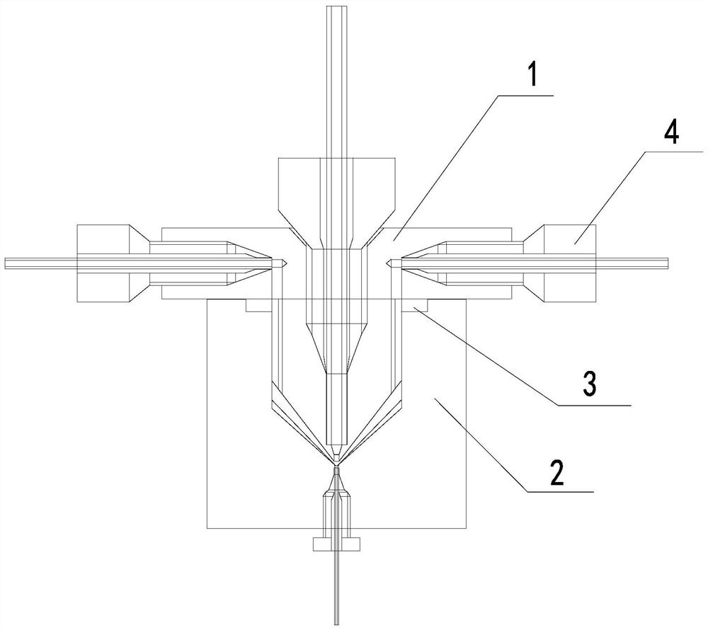
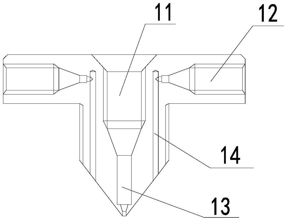
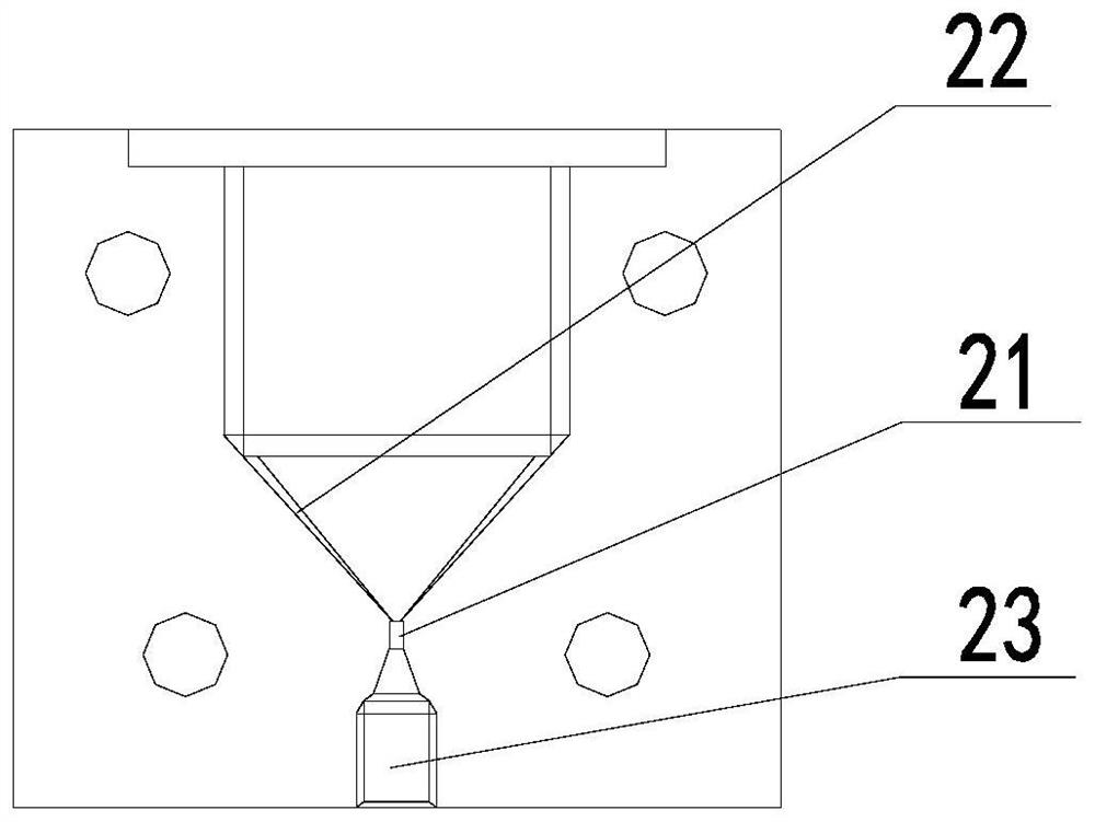
[0023] This embodiment provides a coaxial fluid-liquid path structure, such as Figure 1-3 As shown, it includes a fluid input mechanism 1 and a fluid output mechanism 2 fixedly connected below it. The top of the fluid input mechanism 1 is provided with a main fluid input end 11, and both sides of the fluid input mechanism 1 are respectively provided with a coating At the fluid input end 12, a main fluid flow channel 13 is vertically opened in the middle of the fluid input mechanism 1, and a coating fluid flow channel 14 is vertically opened on both sides of the main fluid flow channel 13. The main fluid input The end 11 is communicated with the main fluid flow channel 13, the coating fluid input end 12 is communicated with the coating fluid flow channel 14 in the corresponding direction; the middle part of the fluid output mechanism 2 is vertically opened with an output flow channel 21, so The output flow channel 21 is concentrically arranged and communicated with the main fl...


PUM


Abstract

The invention provides a coaxial fluid liquid path structure which comprises a fluid input mechanism and a fluid output mechanism fixedly connected to the lower portion of the fluid input mechanism, a main fluid enters a main fluid flow channel from a main fluid input end, a coating fluid enters a coating fluid flow channel from a coating fluid input end, and the coating fluid forms spiral laminar flow through vortex edges. In this way, the main fluid can linearly run in the coating fluid of the spiral laminar flow, the coaxial co-flow effect of two kinds of incompatible fluid is achieved, and material particles in the main fluid can be conveniently analyzed and recognized.

Description

technical field [0001] The invention relates to the application field of fluid pipeline design, in particular to a coaxial fluid-liquid circuit structure. Background technique [0002] When two incompatible fluids co-flow coaxially, they often adopt a crisscross structure or a coaxial nested structure; these two structures have poor effects in practical applications, and the coaxial stability is not strong, so it is difficult to analyze effectively. Signals of particles of matter in a fluid. [0003] Therefore, there is an urgent need for a coaxial fluid-liquid path structure, which can solve the problem of poor co-flow effect of the existing fluid-liquid path structure. SUMMARY OF THE INVENTION [0004] The purpose of the present invention is to provide a coaxial fluid-liquid path structure to solve the problem of poor coaxial co-flow effect of the existing fluid-liquid path structure. [0005] For achieving the above object, the present invention provides following sch...

Claims


Application Information

Patent Timeline
Patent Type & Authority Applications(China)
IPC IPC(8): F16L41/03F16L55/00
CPCF16L41/03F16L55/00
Inventor 吕才树
Owner MEDCAPTAIN MEDICAL TECH
Learn More