Floor radiant heating system

A technology of radiant heating and flooring, applied in the direction of heating system, heating method, flushing, etc., can solve the problems of poor indoor heating effect and achieve the effect of ensuring the heating effect

Pending Publication Date: 2022-06-21
苏州中设建设集团有限公司
View PDF7 Cites 0 Cited by
  • Summary
  • Abstract
  • Description
  • Claims
  • Application Information

AI Technical Summary

Problems solved by technology

[0004] In view of the related technologies mentioned above, the inventor’s hot water pipe transfers a large amount of heat energy to the floor during the process of heating the stone surface, which in turn leads to the defect of poor indoor heating effect

Method used


Image

  • Floor radiant heating system
  • Floor radiant heating system
  • Floor radiant heating system

Examples


Embodiment Construction

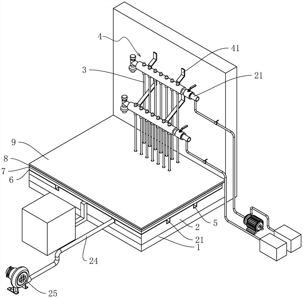
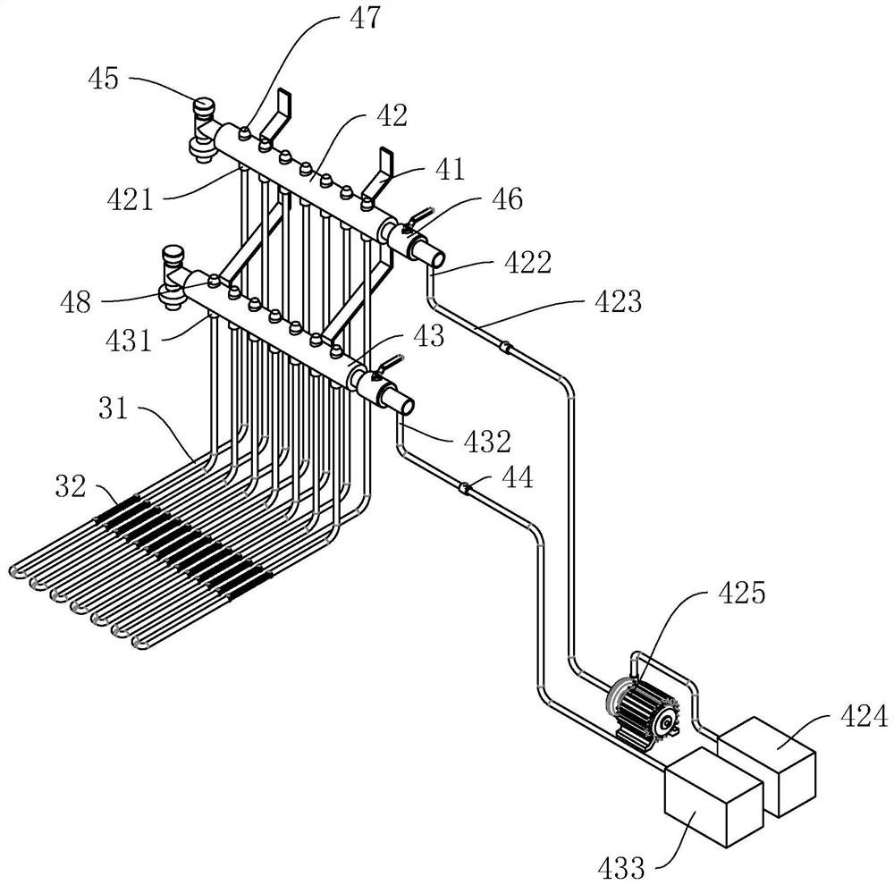
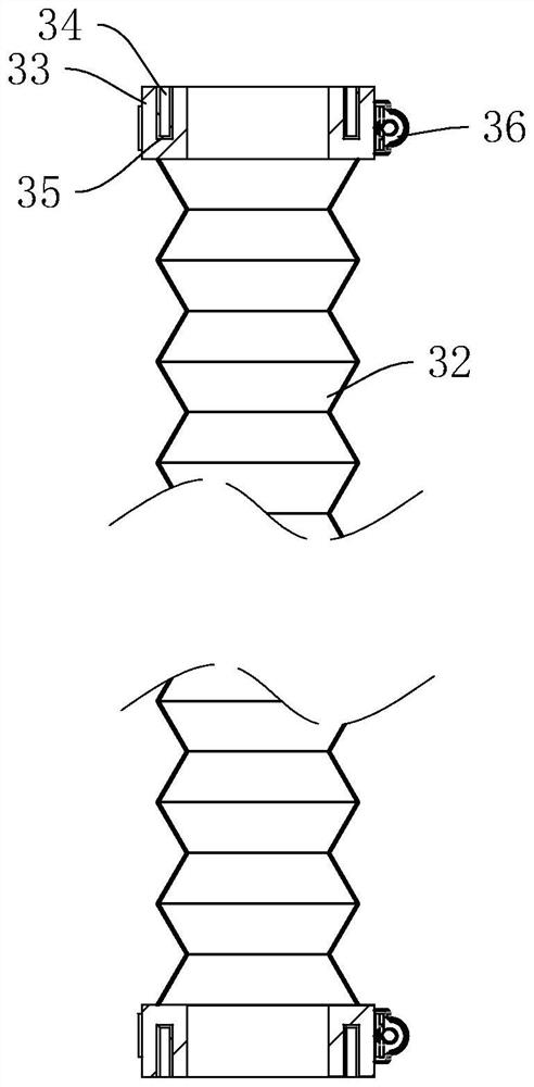
[0035] refer to figure 2 and image 3 , because the indoor space is large, in order to ensure that the warm water pipes 3 can cover the floor 1 as much as possible, each warm water pipe 3 is composed of several PV pipes 31 spliced ​​together. Because hot water needs to be fed intermittently into the PV pipe 31, and the temperature alternates between cold and hot, it is easy to cause the PV pipe 31 to expand and contract repeatedly, and then the gap between the two PV pipes 31 is prone to water leakage. With telescopic connectors. The telescopic connector includes a telescopic bellows 32, the two ends of the telescopic bellows 32 are fixed with connection base sleeves 33, and each connection base sleeve 33 is provided with an annular slot 34 for inserting a PV pipe 31, each slot 34 is fixed with a sealing ring 35, and the section of the sealing ring 35 is U-shaped, so that after the PV tube 31 is inserted into the sealing ring 35, the inner and outer walls of the PV tube 31 ...


PUM


Abstract

The invention relates to the field of house heating, in particular to a floor radiant heating system which comprises a water distributing and collecting device and a plurality of warm water pipes connected with the water distributing and collecting device, a heat preservation layer and a heat storage layer are sequentially arranged on a floor, and the warm water pipes are arranged in the heat storage layer. The heating device has the effect of ensuring the heating effect.

Description

technical field [0001] The application relates to the field of house heating, in particular to a floor radiation heating system. Background technique [0002] Floor radiant heating generally lays heating cables or warm water pipes under the floor, heats the floor by supplying hot water into the pipes or supplying power to the heating cables, and then radiates heat to the room through the floor to achieve the effect of heating. [0003] The current method of industrial hot water heating is to lay warm water pipes on the floor, and then lay a stone surface layer on the warm water pipes, and pass industrial hot water into the warm water pipes, so that the warm water pipes can heat the stone surface layer and pass through the stone surface. The surface layer radiates heat to the room, thereby maintaining the room temperature. [0004] In view of the related technologies mentioned above, the inventors have the defect that a large amount of heat energy is delivered to the floor s...

Claims


Application Information

Patent Timeline
Patent Type & Authority Applications(China)
IPC IPC(8): F24D15/02F24D19/00F24D19/10F28G9/00F28G15/00
CPCF24D15/02F24D19/00F24D19/1006F28G9/00F28G15/003
Inventor 孟飞朋徐杰尹通任功毅陈杰
Owner 苏州中设建设集团有限公司
Why Eureka
Try Eureka