Decompression tank

A technology of pool body and water outlet pool, which is applied in the configuration of water supply pools, buildings, and water supply devices, etc. It can solve the problems of frequent fluctuations in the liquid level of the water tank in the decompression pool, the swaying of the float valve, and the occurrence of water hammer. The risk of frequent fluctuations in the liquid level, the effect of stabilizing the water flow and reducing the number of impacts

Pending Publication Date: 2022-06-24
CHINA HYDROELECTRIC ENGINEERING CONSULTING GROUP CHENGDU RESEARCH HYDROELECTRIC INVESTIGATION DESIGN AND INSTITUTE
View PDF1 Cites 0 Cited by
  • Summary
  • Abstract
  • Description
  • Claims
  • Application Information

AI Technical Summary

Problems solved by technology

[0004] However, when the high-pressure water in the water inlet pipe is sprayed into the water tank of the decompression pool, the liquid level in the water tank of the decompression pool will fluctuate frequently, which will cause the float valve to shake up and down, so the piston rod of the float valve will open and close reciprocally. That is: the piston rod moves in the closing direction for a while, and then moves in the opening direction for a while. When the piston rod moves in the closing direction, water hammer will occur, so there is a risk of water hammer damaging the float valve.

Method used


Image

  • Decompression tank
  • Decompression tank
  • Decompression tank

Examples


Embodiment Construction

[0024] In order to make the purposes, technical solutions and advantages of the embodiments of the present invention clearer, the technical solutions in the embodiments of the present invention will be clearly and completely described below with reference to the accompanying drawings. Obviously, the described embodiments are some, but not all, embodiments of the present invention.

[0025] Accordingly, the following detailed descriptions of embodiments of the present invention are not intended to limit the scope of the claimed invention, but merely represent some embodiments of the present invention. Based on the embodiments of the present invention, all other embodiments obtained by those of ordinary skill in the art without creative efforts shall fall within the protection scope of the present invention.

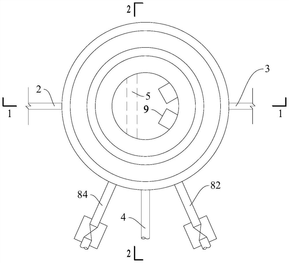
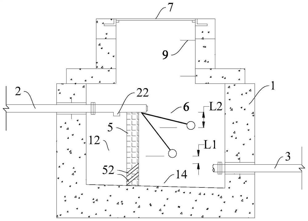
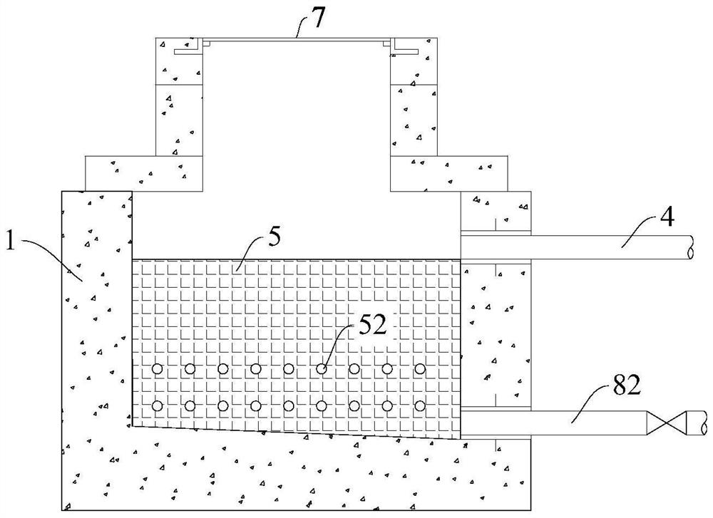
[0026] like Figure 1 to Figure 3 As shown, the decompression pool of the present invention includes a pool body 1, a water inlet pipe 2 and a water outlet pipe 3. The wa...


PUM


Abstract

The invention relates to a decompression pool and belongs to the technical field of decompression of water guiding and conveying pipelines. The pressure reduction pool comprises a pool body, a water inlet pipe and a water outlet pipe, a floating ball valve is arranged on the water inlet pipe and used for opening and closing a water outlet of the water inlet pipe, a partition piece is further arranged in the pressure reduction pool and divides the space in the pressure reduction pool into an energy dissipation pool and a water outlet pool, and a through hole communicated with the energy dissipation pool and the water outlet pool is formed in the partition piece. A water outlet of the water inlet pipe is matched with the energy dissipation pool in position, a floating ball of the floating ball valve is located in the water outlet pool, and the water outlet pipe is communicated with the water outlet pool. When the floating ball valve is closed, the height of the partition piece in the vertical direction is not lower than the highest limit water line corresponding to the highest limit water line of the water outlet tank; when the floating ball valve is completely opened, the highest point of the inner wall of the through hole in the vertical direction is not higher than the lowest limit water line corresponding to the lowest limit water line of the water outlet tank. The device can reduce the risk that the floating ball valve is damaged by the water hammer.

Description

technical field [0001] The invention relates to a decompression tank and belongs to the technical field of decompression of water diversion pipelines. Background technique [0002] The distinctive features of the rural drinking water safety project in the southwest mountainous area are the small scale of construction, scattered villagers, and poor water source conditions, requiring long-distance water delivery to solve the problem of water supply. In engineering design practice, the topography and geological conditions along the water pipeline are responsible, the mountains are high and slopes are steep, the drop is large, and the terrain height difference exceeds 60m. A decompression pool is set up where it is suitable for the terrain. The decompression pool is generally composed of a water inlet pipe, a water outlet pipe, and an overflow pipe. During periods of low water consumption at night, the overflow in the decompression tank is treated. The overflow pipe is generall...

Claims


Application Information

Patent Timeline
Patent Type & Authority Applications(China)
IPC IPC(8): E03B1/02E03B7/07E03B11/10
CPCE03B1/02E03B7/07E03B11/10
Inventor 于晓飞陈友霖王铁虎李美蓉
Owner CHINA HYDROELECTRIC ENGINEERING CONSULTING GROUP CHENGDU RESEARCH HYDROELECTRIC INVESTIGATION DESIGN AND INSTITUTE
Why Eureka
Try Eureka