Electric tool

A technology of electric wood milling and output shaft, which is applied in wood processing appliances, forming/shaping machines, manufacturing tools, etc., to achieve the effects of simple structure, reduced number of impacts, and reasonable impact speed and strength

Inactive Publication Date: 2013-07-31
江苏力普电子有限公司
View PDF6 Cites 0 Cited by
  • Summary
  • Abstract
  • Description
  • Claims
  • Application Information

AI Technical Summary

Problems solved by technology

[0002] Power tools such as electric wood milling and electric drills are usually driven by a motor to rotate the output shaft to drive the tool to rotate for cutting, drilling, etc., but in the long-term use process The tool is easy to wear and needs to be replaced, and it is often necessary to replace tools of various specifications during operation, but the process of disassembling and assembling the tool using a wrench or a tool with similar functions is laborious and time-consuming. At the same time, there are tools such as wrenches. Easy to lose and other problems
British patent GB2351461A discloses a kind of electric wood milling with bevel gears on both the output shaft and the chuck, and the bevel gear on the casing is meshed with the bevel gears on the output shaft and the chuck at the same time, and the casing is manually rotated The bevel gear makes the output shaft and the bevel gear on the collet rotate in opposite directions, so that the collet is released from the output shaft and the tool is replaced. Although this structure of disassembling and assembling the tool solves the problem of tool loss, However, the operator needs to rotate the bevel gear on the casing until the chuck is released, which is laborious and time-consuming
And Chinese patent CN2376354Y discloses a kind of impact self-locking collet structure of gun drill, can hit the collet by the motor rotation of gun drill, makes the collet automatically lock to cutter, yet, this structure needs the operator in gun drill When rotating the impact chuck, it is very laborious to hold the chuck cover without turning it, and this impact self-locking chuck structure is only suitable for power tools with low speed, and the scope of use is also very limited

Method used


Image

  • Electric tool
  • Electric tool
  • Electric tool

Examples


Embodiment Construction

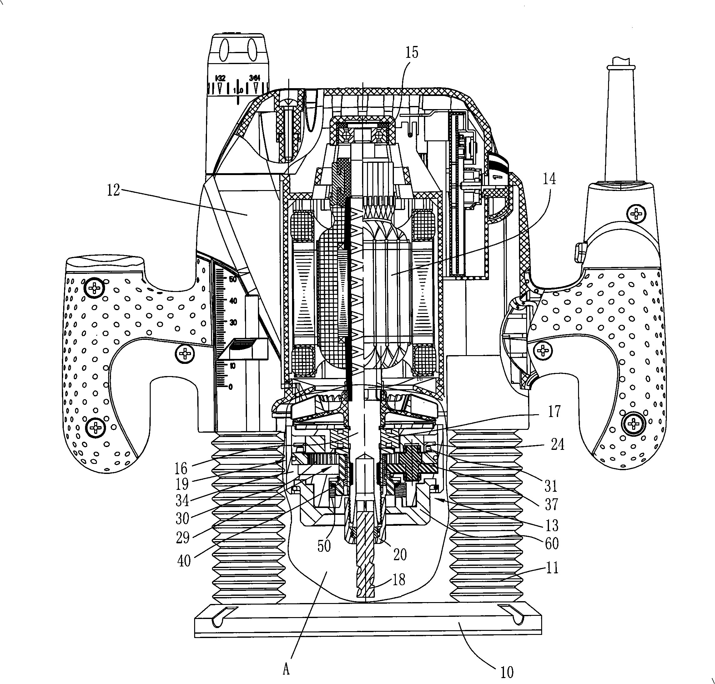
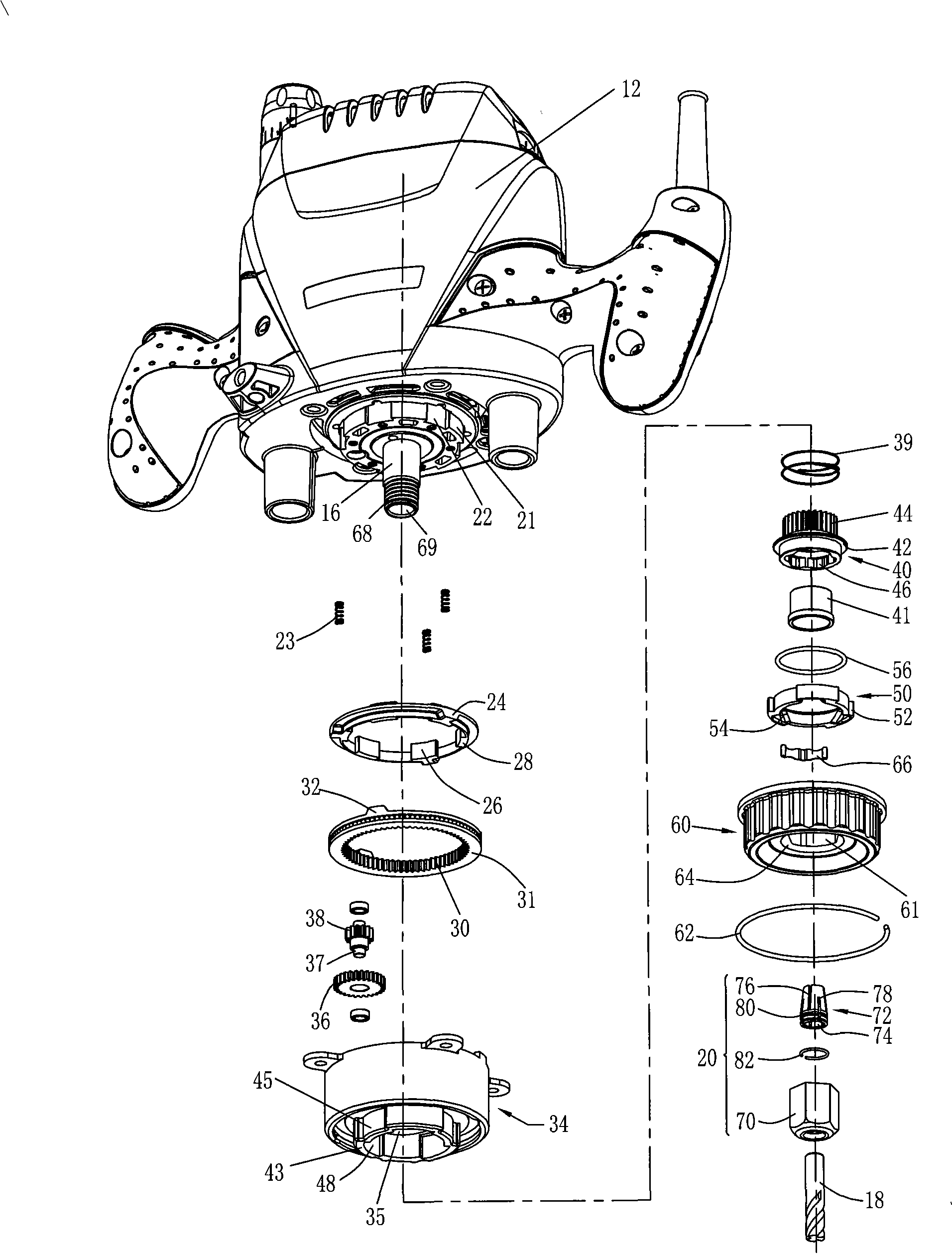
[0045] refer to figure 1 As shown, the electric wood miller in the preferred embodiment of the present invention includes a horizontal base 10, a guide post 11 extending vertically upward from the base 10, a casing 12 that is movably socketed on the guide post 11, and the inside of the casing 12 is hollow. There is a motor 14 placed vertically, and the two ends of the motor 14 are respectively supported on the casing 12 through bearings 15 and 17. The output shaft 16 of the motor 14 protrudes downwards from the casing 12, and connects the output shaft 16 with the tool 18. The polygonal collet 20 is connected, and a spin device 13 is arranged between the casing and the collet, and the spin device 13 includes an impact device 19 that impacts the collet by a driving force of a motor. Impact device 19 comprises impact ring 24, circular ring 31, casing end cover 34 and deceleration mechanism 29, and deceleration mechanism 29 comprises ring gear 30, deceleration shaft 37, guide sle...


PUM


Abstract

The invention discloses an electric router. The electric router comprises a casing, an electric motor, an output shaft, a grip and a spin device, wherein the electric motor is arranged in the casing; the output shaft is driven by the electric motor to rotate; the grip is sleeved on the output shaft, is used to connect the output shaft with a cutter and can perform axial movement relative to the output shaft; and the spin device is connected with the casing in a fitting manner, is fixedly connected with the grip in a rotating manner and can perform axial movement relative to the output shaft when the output shaft rotates. The electric router of the invention adopts the spin device and utilizes the rotation of the output shaft to ensure the grip to perform axial movement for loosing or clamping, thus the cutter can be convenient and fast to dismount; and the electric router of the invention is characterized by simple structure, low cost and convenient operation.

Description

technical field [0001] The invention relates to an electric tool, in particular to an electric tool with a rotary cutter. [0002] Background technique [0003] Power tools such as electric wood milling and electric drills are usually driven by a motor to rotate the output shaft to drive the tool to rotate for cutting, drilling, etc., but the tool is easily worn during long-term use and needs to be replaced It is often necessary to replace tools of various specifications, but the process of disassembling and assembling tools with a wrench or similar functions is laborious and time-consuming. At the same time, tools such as wrenches are easily lost. British patent GB2351461A discloses a kind of electric wood milling with bevel gears on both the output shaft and the chuck, and the bevel gear on the casing is meshed with the bevel gears on the output shaft and the chuck at the same time, and the casing is manually rotated The bevel gear makes the output shaft and the bevel gea...

Claims


Application Information

Patent Timeline
Patent Type & Authority Patents(China)
IPC IPC(8): B27C3/00B27C5/10
Inventor 张士松顾育明
Owner 江苏力普电子有限公司
Why Eureka
Try Eureka