
Three-dimensional imaging method for uniform-speed moving target by uniformly-accelerated-motion double-base ship-borne ISAR (inverse synthetic aperture radar) under low sea condition

A technology of uniform motion and three-dimensional imaging, applied in the field of radar, can solve problems such as inability to complete three-dimensional imaging, and achieve the effects of strong anti-interference ability, good safety performance and long observation distance

Pending Publication Date: 2022-06-24
HARBIN INST OF TECH
View PDF0 Cites 0 Cited by
  • Summary
  • Abstract
  • Description
  • Claims
  • Application Information

AI Technical Summary

Problems solved by technology

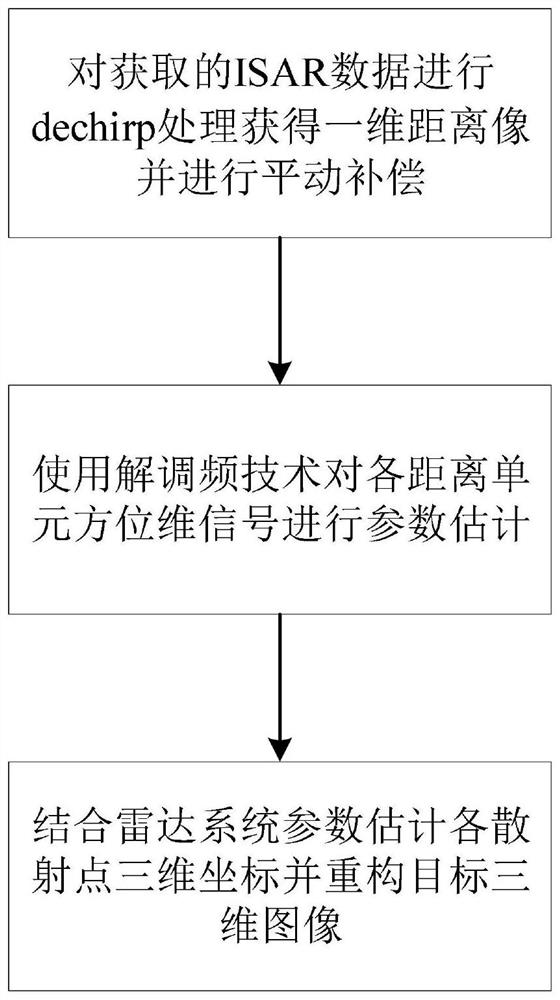
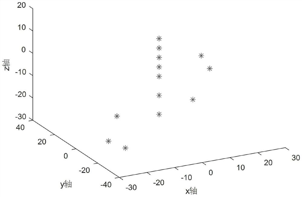
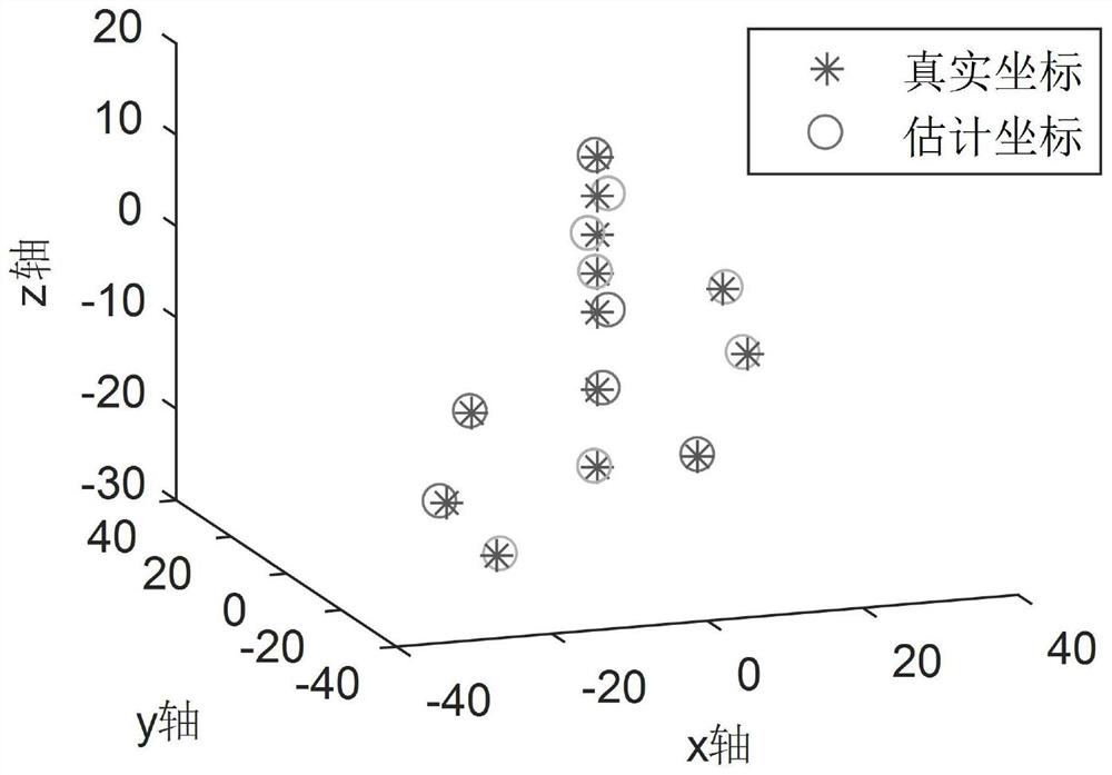
[0003] The purpose of the present invention is to solve the problem that the existing ISAR three-dimensional imaging technology cannot complete the three-dimensional imaging of the shipboard ISAR to the uniform moving target when the radar platform maneuvers under low sea conditions (that is, the uniform acceleration motion), and proposes a low sea condition Three-dimensional imaging method of uniform moving target by double-base shipborne ISAR under uniform acceleration

Method used


Image

  • Three-dimensional imaging method for uniform-speed moving target by uniformly-accelerated-motion double-base ship-borne ISAR (inverse synthetic aperture radar) under low sea condition
  • Three-dimensional imaging method for uniform-speed moving target by uniformly-accelerated-motion double-base ship-borne ISAR (inverse synthetic aperture radar) under low sea condition
  • Three-dimensional imaging method for uniform-speed moving target by uniformly-accelerated-motion double-base ship-borne ISAR (inverse synthetic aperture radar) under low sea condition

Examples


specific Embodiment approach 1

[0021] Specific implementation mode 1: The specific process of a method for 3D imaging of a uniformly moving target by a dual-base shipborne ISAR with uniform acceleration under low sea conditions in this embodiment is as follows:

[0022] Step 1: Obtain the echo signal of the uniformly accelerating dual-base shipborne ISAR to the uniformly moving target under low sea conditions, perform pulse compression on the echo signal to obtain a one-dimensional range image, and perform translation compensation on the one-dimensional range image to obtain translation The compensated one-dimensional distance image;

[0023] There is no three-dimensional swing caused by ocean waves in the ship under low sea conditions, and there is three-dimensional swing caused by ocean waves in the ship under high sea conditions;

[0024] Step 2, using the demodulation frequency method to perform parameter estimation on the azimuth dimension signal of each range unit of the one-dimensional range image af...

specific Embodiment approach 2

[0028] Embodiment 2: The difference between this embodiment and Embodiment 1 is that in step 1, the echo signal of the uniform-acceleration dual-base shipborne ISAR to the target moving at a uniform speed under low sea conditions is obtained, and the echo signal is pulsed. The one-dimensional range image is obtained by compression, and translation compensation is performed on the one-dimensional range image to obtain the one-dimensional range image after translation compensation; the specific process is as follows:

[0029] The linear frequency modulation (LFM) signal transmitted by the ISAR is expressed as:

[0030]

[0031] in is a rectangular function, T p is the pulse width, is fast time, t m is to satisfy t m =Slow time of mT, m is the mth transmitted pulse signal, m=1,2,...,M, M is the total number of transmitted pulse signals, T is the pulse repetition period; t is the full time; f 0 is the carrier frequency of the transmitted signal, the frequency modulat...

specific Embodiment approach 3

[0037] Embodiment 3: The difference between this embodiment and Embodiment 1 or 2 is that the echo signal is subjected to pulse compression to obtain a one-dimensional range image, and translation compensation is performed on the one-dimensional range image to obtain a translation-compensated one-dimensional range image. Dimensional distance image; the specific process is:

[0038] The steps of pulse compression Dechirp processing are:

[0039] Firstly, a linear frequency modulation (LFM) signal with the same parameters as the transmitted linear frequency modulation (LFM) signal with a fixed delay time is used as the reference signal, and the reference signal and the target echo are subjected to frequency difference processing. The one-dimensional distance image can be obtained by Fourier transform (FFT) in the fast time of , and the mathematical expression of the one-dimensional distance image is as follows:

[0040]

[0041] where υ is the distance unit sequence, R pΔ =...


PUM


Abstract

The invention discloses a three-dimensional imaging method for a uniform-speed moving target by a uniformly accelerated motion bistatic ship-borne ISAR (inverse synthetic aperture radar) under a low sea condition, and relates to the three-dimensional imaging method for the uniform-speed moving target by the uniformly accelerated motion bistatic ship-borne ISAR under the low sea condition. The objective of the invention is to solve the problem that the existing ISAR three-dimensional imaging technology cannot complete the three-dimensional imaging of a ship-borne ISAR on a uniform-speed moving target when a radar platform moves in a maneuvering manner under a low sea condition. The method comprises the following steps of: 1, acquiring an echo signal of a uniformly accelerated motion bistatic ship-borne ISAR on a uniform motion target under a low sea condition, performing pulse compression, and performing translation compensation to obtain a one-dimensional range profile after translation compensation; 2, performing parameter estimation on azimuth dimension signals of each distance unit of the one-dimensional distance image after translation compensation by using a demodulation frequency method; and 3, calculating the three-dimensional coordinates of each scattering point according to the azimuth dimension signal parameters of each distance unit and known parameters of a radar system, and reconstructing a target three-dimensional image. The method is applied to the technical field of radars.

Description

technical field [0001] The invention belongs to the technical field of radar, and relates to a three-dimensional imaging method for a uniformly moving target by a uniformly accelerated moving dual-base shipborne inverse synthetic aperture radar under low sea conditions. Background technique [0002] Compared with the inverse synthetic aperture radar (ISAR) two-dimensional imaging technology that can only provide information in two dimensions of the target in the range dimension and the azimuth dimension, the ISAR three-dimensional imaging technology can provide the target in three dimensions (range dimension, azimuth dimension and height) that are perpendicular to each other. dimension) information. The acquisition of the three-dimensional information of the target can provide an important basis for the identification of the target. At present, ISAR three-dimensional imaging technology is mostly based on interference technology (InISAR) using multiple receiving radars (or t...

Claims


Application Information

Patent Timeline
Patent Type & Authority Applications(China)
IPC IPC(8): G01S13/90
CPCG01S13/9064
Inventor 杨佳兴王勇
Owner HARBIN INST OF TECH
Learn More