
Light emitting circuit

A technology of light-emitting circuit and light-emitting unit, which is applied in static indicators, instruments, etc., can solve the problems of light-emitting unit lighting, large leakage current, and affecting display effect, etc.

Pending Publication Date: 2022-06-24
INNOLUX CORP
View PDF0 Cites 0 Cited by
  • Summary
  • Abstract
  • Description
  • Claims
  • Application Information

AI Technical Summary

Problems solved by technology

As the size of the thin film transistor on the display device becomes larger and larger, the leakage current generated when the thin film transistor is not turned on becomes larger and larger, which may even cause the light emitting unit to emit light in the dark state, affecting the presentation of the display effect

Method used


Image

  • Light emitting circuit
  • Light emitting circuit
  • Light emitting circuit

Examples


Embodiment Construction

[0062] Embodiments of the present disclosure are described below. It is intended to illustrate the general principles of the present disclosure, and should not be construed as a limitation of the present disclosure, whose scope should be defined by the claims.

[0063] It will be understood that although the terms "first," "second," "third," etc. may be used herein to describe various elements, components, regions, layers, and / or sections, these elements, components, Regions, layers, and / or sections should not be limited by these terms, and these terms are only used to distinguish between different elements, components, regions, layers, and / or sections. Thus, a first element, component, region, layer, and / or section discussed below could be termed a second element, component, region, layer, and / or section without departing from the teachings of some embodiments of the present disclosure. and / or parts.

[0064] Notably, the following disclosure may provide multiple embodiment...


PUM


Abstract

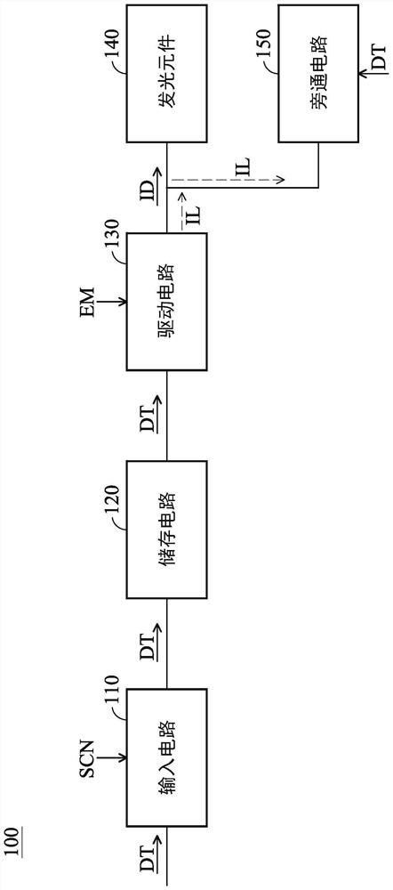
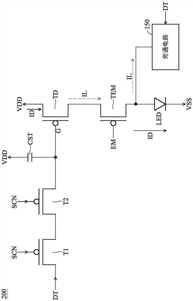
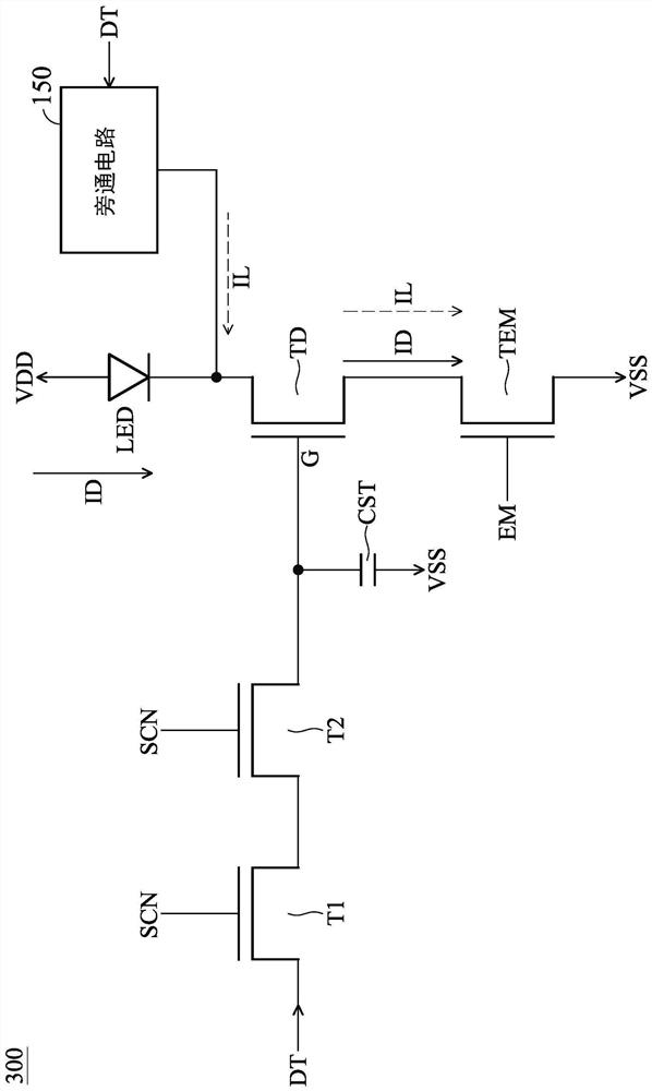
A light emitting circuit includes a light emitting unit, a driving transistor, and a bypass circuit. The driving transistor is used for driving the light-emitting unit. The bypass circuit transfers a current flowing from the driving transistor to the light emitting unit.

Description

technical field [0001] The present disclosure relates to a light-emitting circuit, and more particularly, to a light-emitting circuit with a bypass circuit, which can reduce the possibility of light-emitting units emitting light in a dark state. Background technique [0002] At present, light-emitting unit driving circuits used in display technology mainly include thin-film transistor elements. With the vigorous development of electronic products, the requirements for display quality on electronic products are getting higher and higher. As the size of the thin film transistor on the display device becomes larger and larger, the leakage current generated when the thin film transistor is not turned on becomes larger and larger, which may even cause the light emitting unit to emit light in the dark state, which affects the presentation of the display effect. [0003] Therefore, it is necessary to optimize the leakage current in the light-emitting circuit. SUMMARY OF THE INVE...

Claims


Application Information

Patent Timeline
IPC IPC(8): G09G3/34
CPCG09G3/3406
Inventor 曾名骏郭拱辰陈联祥高启伦
Owner INNOLUX CORP
Learn More