
In-vehicle temperature control system

A technology for temperature regulation and compartments, which is applied to vehicle components, machines/engines, transportation and packaging, etc., and can solve problems such as reduced heating capacity

Active Publication Date: 2021-09-10
TOYOTA JIDOSHA KK
View PDF10 Cites 0 Cited by
  • Summary
  • Abstract
  • Description
  • Claims
  • Application Information

AI Technical Summary

Problems solved by technology

As a result, the heating capacity is temporarily reduced

Method used


Image

  • In-vehicle temperature control system
  • In-vehicle temperature control system
  • In-vehicle temperature control system

Examples


Embodiment Construction

[0034] Embodiments will be described in detail below with reference to the drawings. In addition, in the following description, the same code|symbol is attached|subjected to the same component.

[0035]

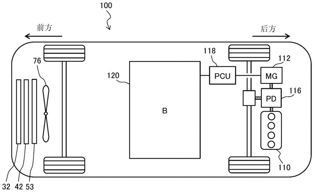
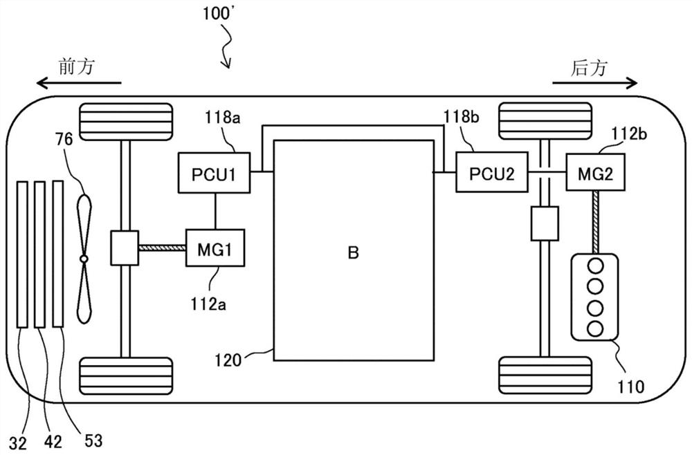
[0036] figure 1 It is a diagram schematically showing the configuration of a vehicle 100 equipped with an in-vehicle temperature regulation system 1 according to an embodiment. exist figure 1 In the graph, the left side represents the front of the vehicle 100 , and the right side represents the rear of the vehicle 100 . Such as figure 1 As shown, a vehicle 100 includes an internal combustion engine 110 , a motor generator (MG: Motor Generator) 112 , and a power split mechanism 116 . Further, vehicle 100 includes power control unit (PCU: Power Control Unit) 118 electrically connected to MG 112 , and battery 120 electrically connected to PCU 118 .

[0037] The internal combustion engine 110 is a prime mover that burns fuel inside the internal combustion engine and conver...


PUM


Abstract

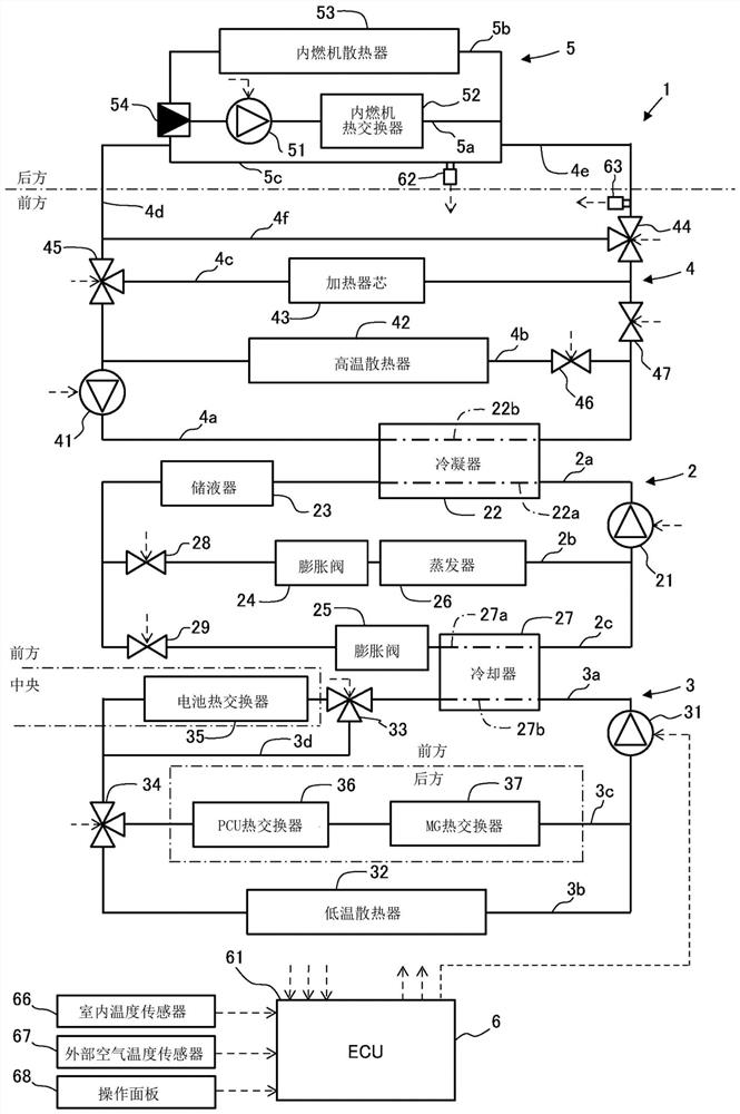
An in-vehicle temperature control system includes: a heater core used to heat an inside of a vehicle cabin using heat of a heat medium; a first heating unit that heats the heat medium using exhaust heat of an internal combustion engine; a thermal circuit configured to circulate the heat medium between the heater core and the first heating unit; a distribution state switching mechanism that switches a distribution state of the heat medium between a first distribution state and a second distribution state; and a control device that controls the distribution state switching mechanism, wherein: the thermal circuit includes a bypass flow path disposed in parallel with the heater core.

Description

technical field [0001] The present disclosure relates to in-vehicle temperature regulation systems. Background technique [0002] There is known an in-vehicle temperature control system that uses a heater core provided in a thermal circuit of the vehicle to heat the interior of the vehicle. In particular, in this on-vehicle temperature regulation system, it is known to use exhaust heat from the internal combustion engine and heat released from a condenser of a refrigerating circuit provided separately from the internal combustion engine to heat the heat medium flowing into the heater core (for example, Japanese Patent Laid-Open 2009-180103). [0003] Furthermore, in terms of vehicle design, it may be necessary to mount the internal combustion engine and the heater core separately. In this case, the piping for the heat medium between the internal combustion engine and the heater core is long. Therefore, when the heat medium heated by the internal combustion engine is inten...

Claims


Application Information

Patent Timeline
Patent Type & Authority Applications(China)
IPC IPC(8): B60H1/00
CPCB60K11/02F01P3/20B60H1/00878B60H1/00885B60H1/00899B60H1/32284B60H1/03B60H1/004F01P2060/08F01P2060/16F01N2240/02F01N2590/11F01N5/02Y02T10/12B60H1/3213B60H1/143B60H1/00278B60H2001/00307B60H2001/00928B60H1/00B60H1/20B60H1/22
Inventor 三好悠司
Owner TOYOTA JIDOSHA KK
Learn More