Battery protection chip, battery assembly and electronic device

A technology to protect chips and batteries, applied in tobacco and other directions, can solve the problems of single function of electronic cigarettes, exhausted batteries, and consumption of battery power, etc., and achieve the effects of improving user experience, increasing use time, and reducing power consumption.

Pending Publication Date: 2022-06-28
XI AN WENXIAN SEMICON TECH CO LTD
View PDF0 Cites 3 Cited by
  • Summary
  • Abstract
  • Description
  • Claims
  • Application Information

AI Technical Summary

Problems solved by technology

[0003] The inventor of the present application found that, regardless of conventional electronic cigarettes or disposable electronic cigarettes, the battery always needs to supply power to the system circuit, the system circuit always supplies power to the airflow sensor, and the system circuit, airflow sensor and other internal circuits will continue to consume battery power
However, the power of the battery is certain. When the e-cigarette with a battery with a preset power is manufactured at the production site, the e-cigarette will be transported (such as by sea), stored for a long time, and finally sold to the end user. When the end user When using a brand new e-cigarette for the first time, due to the long-term transportation and storage of the e-cigarette, the battery may be exhausted or consumed a lot due to the consumption of the internal circuit of the e-cigarette, so that the end user cannot directly pick up the e-cigarette Just use or use e-cigarettes for a short period of time to run out of power. Due to the urgency and persistence of smoking, the experience of users using e-cigarettes is worse than that of traditional cigarettes.
Moreover, the existing electronic cigarettes have relatively single functions

Method used


Image

  • Battery protection chip, battery assembly and electronic device
  • Battery protection chip, battery assembly and electronic device
  • Battery protection chip, battery assembly and electronic device

Examples


no. 1 example

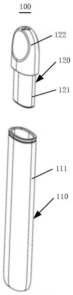
[0098] In this example, see figure 1 , figure 2 , the electronic cigarette 100 is a conventional electronic cigarette, and its pod 120 is a replaceable pod. When the pod 120 is used up, the user can remove the old pod 120 and replace it with a new pod 120; The battery 2400 is a rechargeable battery 2400, such as a lithium battery, a nickel-cadmium battery, a nickel-metal hydride battery, etc. The cigarette rod 110 includes a charging interface, and the charging interface is electrically connected to the battery 2400 through the battery protection circuit 2000, and the charging interface is used for external charging The charger is electrically connected, for example, the charger can provide a voltage and current of 5V / 1A or 5V / 2A, etc., to charge the battery 2400 . When the power of the battery 2400 in the electronic cigarette is low, the user can connect the charger through the charging interface to charge the battery 2400 . Since the pod 120 is a replaceable cigarette, th...

no. 2 example

[0139] see Figure 13 , Figure 13 is a circuit block diagram of the electronic device according to the second embodiment of the present application. This embodiment is similar to the first embodiment, so the parts not described in this embodiment can be referred to the first embodiment. The difference is that the first switch unit 2300 is externally placed and the first switch unit 2300 is placed above.

[0140] See Figure 13 In this embodiment, the first switch unit 2300 is placed outside and the first switch unit 2300 is placed above, that is, the first switch unit 2300 is located outside the battery protection module 2100 . The first end of the first switch unit 2300 is electrically connected to the positive electrode of the battery 2400 , the second end of the first switch unit 2300 is electrically connected to the system end VM and the system circuit 131 respectively, and the control end of the first switch unit 2300 is connected to the battery protection module The ...

no. 3 example

[0145] see Figure 14 , Figure 14 This is the circuit block diagram of the electronic device according to the third embodiment of the present application. This embodiment is similar to the first and second embodiments. Therefore, for the parts not described in this embodiment, reference can be made to the previous embodiments. This embodiment is similar to the first and second embodiments. The main difference between the two embodiments is that the battery protection module 2100 further includes a first shipping exit terminal QC1.

[0146] Please refer to Figure 14 and Figure 15 , in this embodiment, the second shipping exit terminal QC2 is not directly connected to the system side VM. Specifically, the battery protection module 2100 further includes a first shipping exit terminal QC1, the first shipping exit terminal QC1 is electrically connected to the second shipping exit terminal QC2, and the first shipping exit terminal QC1 is connected to the first NOT gate 2121. ...


PUM


Abstract

The invention provides a battery protection chip which comprises a battery protection module and a first switch unit, the battery protection module comprises a power supply pin, a power supply grounding pin, an over-discharge voltage protection unit, a discharge overcurrent protection unit, a logic control unit and a system pin, and the battery protection chip further comprises a capacitance detection module, the capacitance detection module is electrically connected with the power supply pin and the power supply grounding pin, the capacitance detection module comprises a capacitance detection unit and a capacitance detection pin, the capacitance detection unit is electrically connected with the capacitance detection pin, the capacitance detection pin is used for being electrically connected with the detection electrode, and the capacitance detection module is further electrically connected with the battery protection module; when the capacitance detection unit detects capacitance change, the capacitance detection module sends a shipping control signal to the battery protection module, the battery protection module enters or exits from a shipping mode, and in the shipping mode, the first switch unit is switched off to enable the battery to stop supplying power to the system circuit. The invention further provides a battery assembly and an electronic device.

Description

technical field [0001] The present application relates to the field of battery technology, and in particular, to a battery protection chip, a battery assembly and an electronic device. Background technique [0002] Existing electronic cigarettes usually include two parts: a cigarette rod and a pod with an atomizer. The pod stores the e-juice, and the atomizer atomizes the e-liquid when it works; the cigarette rod is equipped with a battery, a system circuit and an airflow sensor. (such as a microphone), the battery is electrically connected to the system circuit, and the system circuit is electrically connected to the atomizer and the airflow sensor. When the airflow sensor detects the airflow caused by the user's smoking, the system circuit determines that the user has a smoking action, and the system The circuit controls the output power of the atomizer, and the atomizer heats and atomizes the e-liquid to realize smoke. [0003] The inventor of the present application fou...

Claims


Application Information

Patent Timeline
Patent Type & Authority Applications(China)
IPC IPC(8): A24F40/40A24F40/50A24F40/53A24F40/51
CPCA24F40/40A24F40/50A24F40/53A24F40/51
Inventor 宋利军贺玉婷宋朋亮刘鸿飞周虹安
Owner XI AN WENXIAN SEMICON TECH CO LTD
Why Eureka
Try Eureka