Multi-contact mechanical spot welding equipment

A spot welding equipment, multi-contact technology, applied in welding equipment, resistance welding equipment, metal processing equipment and other directions, can solve problems such as easy damage to the user's body, and achieve the effect of high applicability, simple use, and improved operating environment

Pending Publication Date: 2022-06-28
YANTAI NANSHAN UNIV
View PDF0 Cites 0 Cited by
  • Summary
  • Abstract
  • Description
  • Claims
  • Application Information

AI Technical Summary

Problems solved by technology

[0004] The purpose of the present invention is to solve the shortcoming of easily damaging the user's body in the prior art, and propose a multi-contact mechanical spot welding equipment

Method used


Image

  • Multi-contact mechanical spot welding equipment
  • Multi-contact mechanical spot welding equipment
  • Multi-contact mechanical spot welding equipment

Examples


Embodiment 1

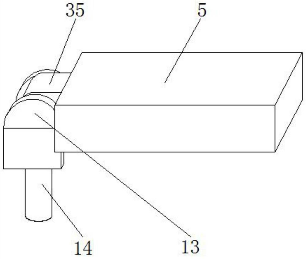
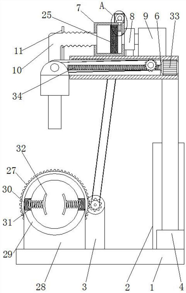
[0027] refer to Figure 1-4 , a multi-contact mechanical spot welding equipment, including a base 1, a vertical box 2 is arranged on the base 1, a motor base 3 is arranged on the base 1, a cylinder 4 is arranged in the vertical box 2, and the telescopic rod of the cylinder 4 is fixedly installed There is a horizontal plate 5, a horizontal slot 6 is opened in the horizontal plate 5, a storage box 7 is arranged on the horizontal plate 5, a fan 8 is arranged on one side of the storage box 7, an adsorption box 9 is arranged on the fan 8, and one side of the storage box 7 is provided. A stack tube 10 is arranged on the side, a first motor 15 is arranged on the motor base 3, a rotating rod 16 is fixedly installed on the output shaft of the first motor 15, a filter mechanism is arranged on the horizontal plate 5, and a clamping mechanism is arranged on the base 1 , a second motor 33 is arranged in the horizontal groove 6, a threaded rod 34 is fixedly installed on the output shaft of ...

Embodiment 2

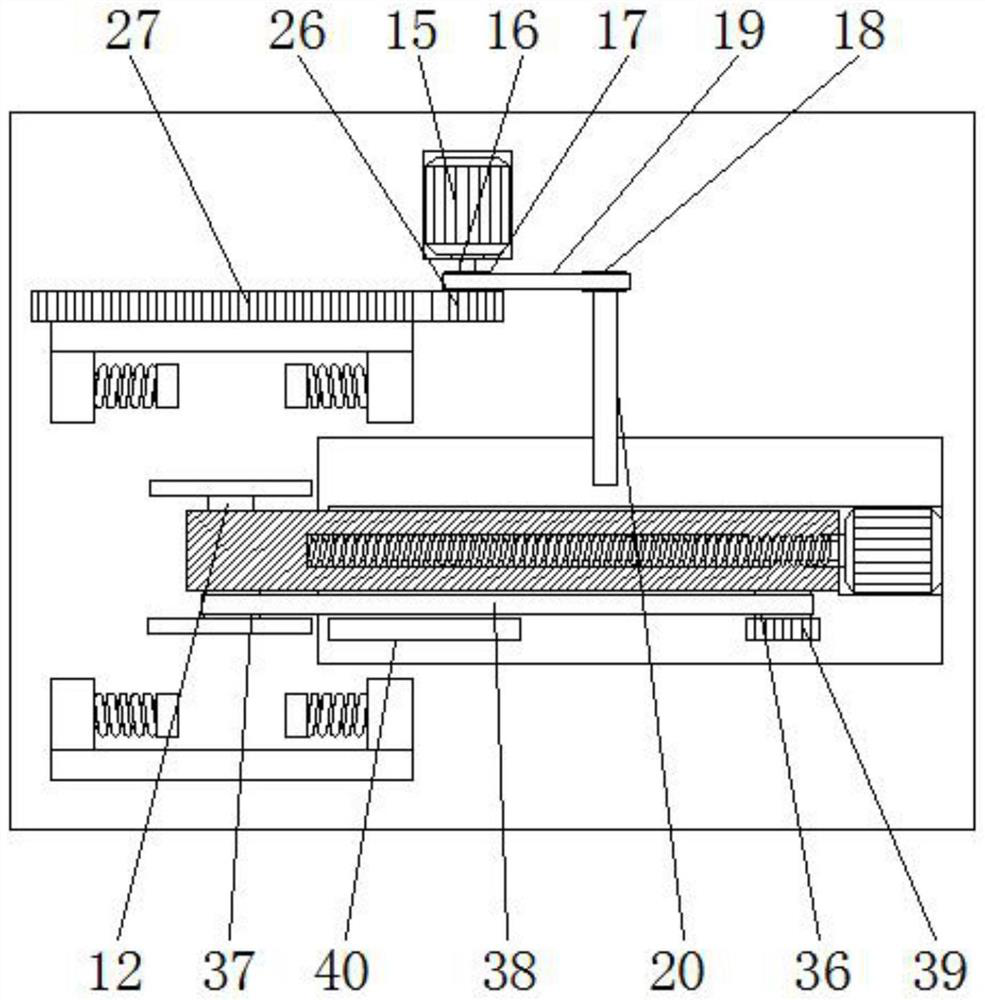
[0039] refer to Figure 5-6 , the difference from the first embodiment is that the filter mechanism includes a first pulley 17, the first pulley 17 is fixedly connected with the rotating rod 16, the rotating rod 20 is rotatably installed on the storage box 7, and the rotating rod 20 is fixedly installed with a second belt The same first belt 19 is installed on the pulley 18, the first pulley 17 and the second pulley 18, the half gear 41 is fixedly installed on the rotating rod 20, and the storage box 7 is provided with a straight rail, which is slidably installed on the straight rail. There is a toothed frame 42 , the toothed frame 42 is engaged with the half gear 41 , the storage box 7 is provided with a filter screen 25 , and the filter screen 25 and the toothed frame 42 cooperate with each other.

[0040] Working principle: when spot welding two round pipes, clamp the two round pipes between the four clamp plates 32, and make the two round pipes connect, under the cooperati...


PUM


Abstract

The invention belongs to the technical field of spot welding equipment, particularly relates to multi-contact mechanical spot welding equipment, and aims to solve the problem that the existing multi-contact mechanical spot welding equipment is easy to damage the body of a user, the multi-contact mechanical spot welding equipment comprises a base, a vertical box is arranged on the base, a motor base is arranged on the base, and an air cylinder is arranged in the vertical box; a transverse plate is fixedly mounted on a telescopic rod of the air cylinder, a transverse groove is formed in the transverse plate, a storage box is arranged on the transverse plate, a fan is arranged on one side of the storage box, an adsorption box is arranged on the fan, a folding pipe is arranged on one side of the storage box, and a first motor is arranged on the motor base; a rotating rod is fixedly installed on an output shaft of the first motor, a filtering mechanism is arranged on the transverse plate, and the filtering mechanism comprises a first belt pulley. The welding device can conduct welding in different directions, is high in applicability, can adsorb dust and improve the operation environment, and is easy to use and convenient to operate.

Description

technical field [0001] The invention relates to the technical field of spot welding equipment, in particular to a multi-contact mechanical spot welding equipment. Background technique [0002] Spot welding refers to a welding method in which a cylindrical electrode is used during welding to form a welding spot between the contact surfaces of two overlapping workpieces. During spot welding, pressure is applied to make the workpiece in close contact, and then the current is turned on. Under the action of resistance heat, the contact of the workpiece is melted, and a solder joint is formed after cooling. [0003] The spot welding equipment in the prior art requires the user to be close to the welding position during welding, and the heat and light generated by the welding will affect the user's health. Therefore, we propose a multi-contact mechanical spot welding equipment. SUMMARY OF THE INVENTION [0004] The purpose of the present invention is to propose a multi-contact m...

Claims


Application Information

Patent Timeline
Patent Type & Authority Applications(China)
IPC IPC(8): B23K11/11B23K11/31B23K11/36
CPCB23K11/11B23K11/31B23K11/36
Inventor 姜丽军朱鹏程栾树栋赵俊凤王萍谢撰业
Owner YANTAI NANSHAN UNIV
Why Eureka
Try Eureka