Traction and brake fusion system and method based on two-stage control architecture

A secondary control and architecture technology, applied to signal indicators on vehicles, railway signals and safety, railway signals, etc., can solve problems such as low comfort, braking force fluctuations, and lengthy control links, and achieve anti-skid and air defense transfer, improve control performance, and shorten the control link

Pending Publication Date: 2022-06-28
CRRC QINGDAO SIFANG ROLLING STOCK RES INST
View PDF9 Cites 0 Cited by
  • Summary
  • Abstract
  • Description
  • Claims
  • Application Information

AI Technical Summary

Problems solved by technology

[0003] The purpose of the embodiments of the present invention is to provide a traction braking fusion system and method based on a two-level control architecture, so as to solve the problems in the prior art that the control link of the traction braking function is lengthy and the coordination between the systems is poor, resulting in poor control performance of the vehicle. Weak, braking force fluctuations, long braking distance, low comfort

Method used


Image

  • Traction and brake fusion system and method based on two-stage control architecture
  • Traction and brake fusion system and method based on two-stage control architecture
  • Traction and brake fusion system and method based on two-stage control architecture

Examples


Embodiment Construction

[0039] The present application will be further described in detail below with reference to the accompanying drawings and embodiments. It should be understood that the specific embodiments described herein are only used to explain the related invention, but not to limit the invention. In addition, it should be noted that, for the convenience of description, only the parts related to the related invention are shown in the drawings.

[0040] It should be noted that the embodiments in the present application and the features of the embodiments may be combined with each other in the case of no conflict. The present application will be described in detail below with reference to the accompanying drawings and in conjunction with the embodiments.

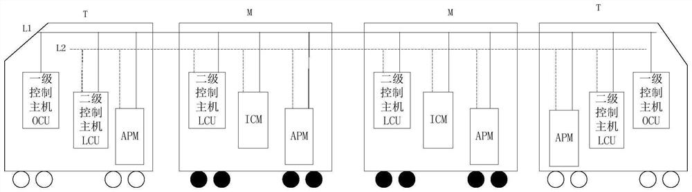
[0041] figure 1 A frame diagram of a traction brake fusion system based on a two-level control architecture provided for an embodiment of the present invention. like figure 1 As shown, the traction brake fusion system based on the two-l...


PUM


Abstract

The invention provides a traction and braking fusion system based on a two-stage control architecture, which comprises the following steps: when a first-stage control host has a control right, receiving a network signal, and distributing traction force or braking force of a whole train according to the network signal; or when the second-level control host has the control right, the hard wire signal is received, and the traction force or the braking force of the vehicle is calculated; then, according to the impact rate limitation, the traction target value of each period is sent to the ICM through the vehicle network; or the target value of the electric braking force is sent to the ICM through the vehicle network; or the target value of the electric braking force is sent to the ICM, and the target value of the friction braking force is sent to the APM; the ICM collects actual traction force, or the ICM collects actual electric braking force, or the ICM collects actual electric braking force, the APM collects actual friction braking force, and the actual traction force, the actual electric braking force and the actual friction braking force are sent to the first-stage control host or the second-stage control host; and the first-stage control host or the second-stage control host is enabled to perform force distribution again.

Description

technical field [0001] The invention relates to the technical field of fusion control, in particular to a traction braking fusion system and method based on a two-level control architecture. Background technique [0002] At present, the traction braking system of rail transit vehicles is relatively independent. The traction management control of the vehicle is handled in a distributed manner by the traction controllers of each vehicle, and the braking management control of the vehicle is handled in a distributed manner by the brake controllers of each vehicle. In the process, the train management and control system (Train Control and Management System, TCMS) only undertakes the limited information transmission function, and does not realize the information sharing among the systems and the centralized management of the traction braking of the whole train. The links are long and the coordination between systems is poor, resulting in weak vehicle control performance, fluctuati...

Claims


Application Information

Patent Timeline
Patent Type & Authority Applications(China)
IPC IPC(8): B61L15/00
CPCB61L15/00B61L15/0081B61L15/0072
Inventor 徐恭德王宏源崔雷冯勇马法运苗峰
Owner CRRC QINGDAO SIFANG ROLLING STOCK RES INST
Why Eureka
Try Eureka