[0026] The technical solutions in the embodiments of the present invention will be clearly and completely described below with reference to the accompanying drawings in the embodiments of the present invention. Obviously, the described embodiments are only a part of the embodiments of the present invention, but not all of the embodiments. Based on the embodiments of the present invention, all other embodiments obtained by those of ordinary skill in the art without creative work fall within the protection scope of the present invention.
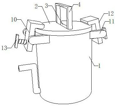
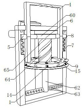
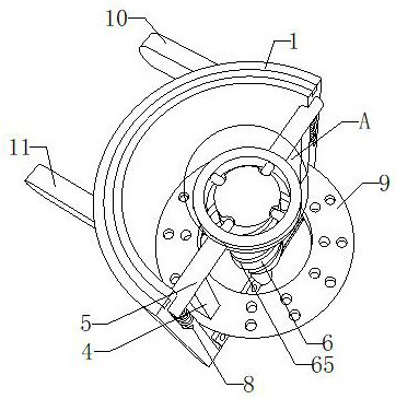
[0027] see Figure 1 to Figure 5 , the present invention provides a technical solution: a multifunctional medical feeding device for pediatric nursing, comprising a cylinder 1, a cover plate 2 is fixedly connected to the top surface of the cylinder 1, and a long groove 3 is opened on the top surface of the cover plate 2 The side of the inner wall of the long groove 3 is slidably connected with a C-shaped rod 4, the middle of the opposite side of the two vertical rods of the C-shaped rod 4 is fixedly inserted with a cross rod 5, and the opposite end of the two horizontal rods 5 is fixedly connected with a stirring mechanism 6;
[0028] The middle of the inner wall of the cylinder 1 is provided with a chute 7, the side of the inner wall of the chute 7 is slidably connected with the side of the cross bar 5, the side of the inner wall of the chute 7 is fixedly connected with a compression spring 8, and the top of the compression spring 8 is connected to the side of the cross bar 5. The lower side of the cross bar 5 is fixedly connected;
[0029] The bottom ends of the two vertical rods of the C-shaped rod 4 are fixedly connected with a scraper 9, the bottom surface of the scraper 9 is fixedly connected with six springs 14, and the bottom ends of the six springs 14 are fixedly connected with a scraper frame 15. The upper side of the side is fixedly connected with a fixing mechanism 10 .
[0030] In this embodiment, as figure 2 , image 3 , Figure 4 and Figure 5 As shown, the stirring mechanism 6 includes a circle 60, the left and right sides of the circle 60 are respectively fixedly connected with the opposite sides of the two cross bars 5, and the sides of the inner wall of the circle 60 are fixedly connected with four sliders 61, and the four sliders 61 Isometric distribution in a ring;
[0031] The bottom surface of the inner wall of the cylinder 1 is fixedly connected with a rotating rod 62, the lower sides of the left and right sides of the rotating rod 62 are fixedly connected with a stirring rod 63, the top surface of the rotating rod 62 is fixedly connected with a cylinder 64, and the side of the cylinder 64 is provided with four arcs The four arc-shaped grooves 65 are equidistant annular parts, and the sides of the four sliders 61 are respectively slidably connected to the sides of the inner wall of the four arc-shaped grooves 65, and the sliders 61 slide to the lower side of the inner wall of the arc-shaped groove 65. , can drive the cylinder 64 and the stirring rod 63 to rotate.
[0032] In this embodiment, as figure 1 , figure 2 , image 3 and Figure 5 As shown, the fixing mechanism 10 includes a long strip 11, the number of the long strips 11 is four, and two of the four long strips 11 are a group of two opposite sides respectively fixedly connected to the upper sides of the front and rear sides of the cylinder 1, Two of the four long strips 11 are a set of L-shaped pressure strips 12 are rotatably connected on opposite sides, and T-shaped threaded rods 13 are threaded on the sides of the vertical strips of the L-shaped pressure strips 12. One end of the T-shaped threaded rods 13 is connected to the circle. The side surface of the cylinder 1 is slidably connected, and the cover plate 2 can be fixed by the horizontal bar of the L-shaped bead 112 by rotating the T-shaped threaded rod 13 .
[0033] In this embodiment, as figure 1 , figure 2 , image 3 , Figure 4 and Figure 5 As shown, the length of the vertical rod of the C-shaped rod 4 is equal to the length of the inner wall side of the cylinder 1, and the length of the inner wall side of the chute 7 is half the length of the vertical rod of the C-shaped rod. The vertical rod of the C-shaped rod 4 drives the horizontal rod 5 to move to When the bottom surface of the inner wall of the chute 7, the vertical rod of the C-shaped rod 4 will simultaneously drive the scraper 9 and the scraper frame 15 to move to the lower side of the inner wall of the cylinder 1, and scrape off the residual liquid medicine on the side of the inner wall of the cylinder 1.
[0034] In this embodiment, as figure 1 , figure 2 , image 3 and Figure 5 As shown, the side surface of the scraper 9 is slidably connected to the side surface of the inner wall of the cylinder 1. The shapes of the scraper 9 and the scraper frame 15 are both circular truncated, and the side of the scraper 9 is provided with a through groove, and the circular truncated scraper 9 and The side of the scraping frame 15 is relatively sharp, and it is more convenient to scrape off the viscous liquid medicine on the side of the inner wall of the cylinder 1 .
[0035] In this embodiment, as figure 2 As shown, the number of stirring rods 63 is two, and the angle between the opposite sides of the two stirring rods 63 is 30°, and the two stirring rods 63 on the inclined plane can quickly stir and mix the granular liquid medicine evenly.
[0036] In this embodiment, as figure 1 , figure 2 , image 3 and Figure 5 As shown, the lower side of the rotating rod 62 is fixedly sleeved with a bearing, the outer ring of the bearing is fixedly connected with the bottom surface of the inner wall of the cylinder 1, and the bearing reduces the friction coefficient generated when the lower side of the rotating rod 62 rotates on the bottom surface of the inner wall of the cylinder 1, Increased its stability when turning.
[0037] In this embodiment, as figure 1 , figure 2 , image 3 and Figure 5 As shown, the lower side of the left side of the cylinder 1 is provided with a water outlet, the side of the inner wall of the water outlet is fixedly connected with a Z-shaped straw, and the angle between the left side of the bottom surface of the inner wall of the cylinder 1 and the ground is 25°;
[0038] The top surface of the cylinder 1 is provided with a circular groove, the bottom surface of the cover plate 2 is fixedly connected with a rubber ring, the side surface of the rubber ring is fixedly connected to the side surface of the inner wall of the circular groove, and the cylinder 1 with the inclined surface of the inner wall is convenient to move the liquid medicine to the cylinder. 1. One side of the inner wall makes the cleaning of the cylinder 1 more convenient, and the rubber ring ensures the sealing between the cover plate 2 and the top surface of the cylinder 1.
[0039] The use method and advantages of the present invention: the use method of the multifunctional medical pediatric nursing drug feeding device, the working process is as follows:
[0040] like figure 1 , figure 2 , image 3 , Figure 4 , Figure 5 As shown: Move the C-shaped rod 4 to the lower side of the cylinder 1, so that the two vertical rods of the C-shaped rod 4 drive the two horizontal rods 5 to move to the lower side of the inner wall of the chute 7, and squeeze the compression spring 8 , so that the two cross bars 5 drive the circle 60 and the slider 61 to move downward, so that the side of the slider 61 is in contact with the side of the inner wall of the arc-shaped groove 65, so that the side of the slider 61 moves to the lower side of the inner wall of the arc-shaped groove 65 , so that the cylinder 64 drives the rotating rod 62 to rotate, so that the two stirring rods 63 drive the granular medicine to rotate, thereby reducing the possibility of children drinking the granular medicine, making the medicine feeding device more convenient for children.
[0041] Rotate the two T-shaped threaded rods 13 counterclockwise, so that the opposite ends of the two T-shaped threaded rods 13 cross the side of the cylinder 1 from a state of conflict to a non-contact state, so that the two L-shaped pressure bars 12 are horizontal. The strip changes from the closed state on the top surface of the cylinder 1 to the open state, so that the lower sides of the two L-shaped pressure strips 12 are released from the fixed state of the cover plate 2, so that the cover plate 2 can drive the rubber ring from the circle. The top surface of the cartridge 1 is taken out, so that the disassembly of the medicine feeding device is more convenient.
[0042] By pressing the C-shaped rod 4 downward, the two vertical rods of the C-shaped rod 4 drive the two transverse rods to move to the lower side of the inner wall of the chute 7, and the compression spring 8 is squeezed. At the same time, the two C-shaped rods 4 The vertical rod drives the scraper 9 to move to the lower side of the inner wall of the cylinder 1, so that the cylinder 1 drives the scraper frame 15 to move to the lower side of the inner wall of the cylinder 1 through the spring 14, so that the side surface of the scraper frame 15 and the remaining viscous liquid move. The contact produces resistance, so that the scraper frame 15 squeezes the spring 14, so that the scraper frame 15 vibrates downward, so that the scraper 9 and the scraper frame 15 move up and down, so that the medicine feeding device has a relatively viscous residue on the inner wall of the cylinder 1. The cleaning of the liquid is relatively simple.
[0043] The foregoing has shown and described the basic principles, main features and advantages of the present invention. Those skilled in the industry should understand that the present invention is not limited by the above-mentioned embodiments, and the above-mentioned embodiments and descriptions are only preferred examples of the present invention, and are not intended to limit the present invention, without departing from the spirit and scope of the present invention. Under the premise of the present invention, there will be various changes and improvements, and these changes and improvements all fall within the scope of the claimed invention. The claimed scope of the present invention is defined by the appended claims and their equivalents.