
Hot bending die and hot bending processing method

A processing method and mold technology, which can be applied to household appliances, other household appliances, optical components, etc., can solve the problems of high processing cost, high mold processing cost and difficulty, and achieve the effect of reducing mold cost.

Pending Publication Date: 2022-07-01
NINGBO SUNNY AUTOMOTIVE OPTECH
View PDF0 Cites 0 Cited by
  • Summary
  • Abstract
  • Description
  • Claims
  • Application Information

AI Technical Summary

Problems solved by technology

[0004] 1. The appearance requirements of the mold surface are relatively high, and the mold processing cost is relatively high;
[0005] 2. The surface precision requirements of the upper mold core and the lower mold core are very high, and the processing cost is high and difficult;
[0006] 3. The upper mold core and the lower mold core have high precision requirements for mold clamping, and the compression molding mold needs to move up and down, and it is currently impossible to achieve high-precision matching;
[0007] 4. The surface shape of the lens after molding is irregular, and it is not easy to compensate for the surface shape of the mold;
[0008] 5. When the prefabricated part is placed, the position of the prefabricated part cannot be guaranteed to be placed in the center of the mold;

Method used


Image

  • Hot bending die and hot bending processing method
  • Hot bending die and hot bending processing method
  • Hot bending die and hot bending processing method

Examples


Embodiment Construction

[0085] Example embodiments will now be described more fully with reference to the accompanying drawings. However, example embodiments can be embodied in various forms and should not be construed as limited to the embodiments set forth herein. Rather, these embodiments are provided so that this disclosure will be thorough and complete, and will fully convey the concept of example embodiments to those skilled in the art. The embodiments described below with reference to the accompanying drawings are exemplary, only used to explain the present invention, and should not be construed as a limitation of the present invention. The same reference numerals in the drawings denote the same or similar structures, and thus their repeated descriptions will be omitted.

[0086] In the description of the present invention, it should be understood that the terms "first" and "second" are only used for description purposes, and cannot be interpreted as indicating or implying relative importance...


PUM

PropertyMeasurementUnit
thicknessaaaaaaaaaa

Abstract

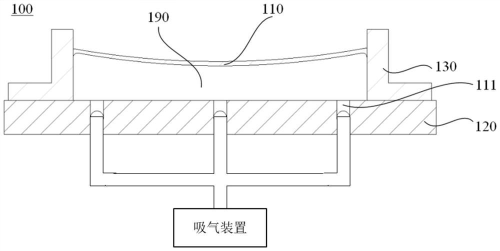
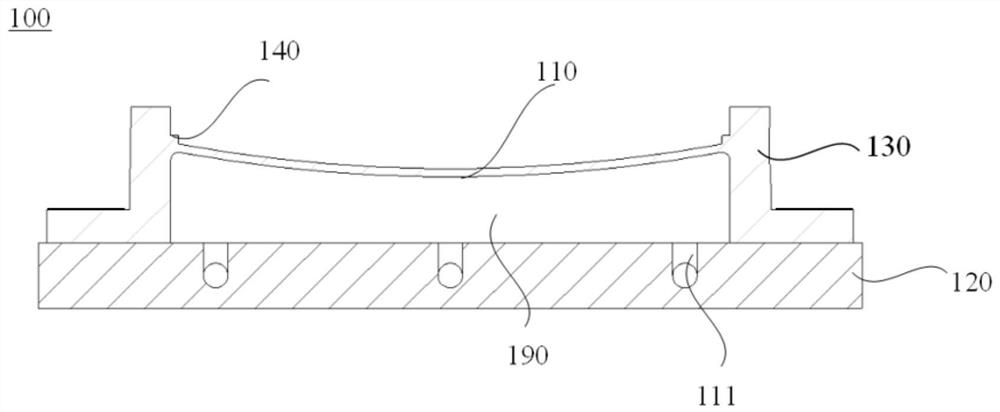
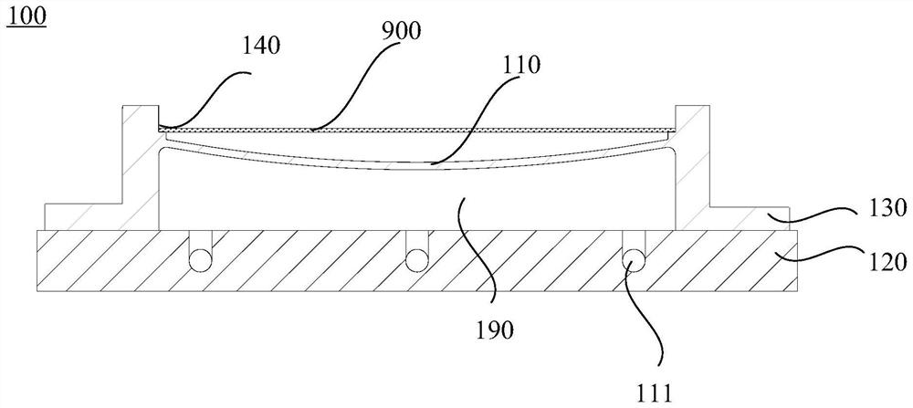
The invention provides a hot bending die and a hot bending machining method. The hot bending die comprises a first die core assembly. The first mold core assembly comprises a first forming face, a first air cavity with the first forming face as a side wall and at least one first air channel. A plurality of pores are distributed in the first forming surface; the first air cavity is communicated with an air suction device through the first air channel. According to the hot bending die, only one die core assembly needs to be provided with the air suction cavity, when a lens is formed through the air suction cavity and the die core with the hole, pressure difference is formed on the two surfaces of a to-be-machined material, the to-be-machined material is tightly attached to the surface of the die core through the pressure difference, and the forming effect can be achieved without additionally arranging another die core; and the die cost is greatly reduced.

Description

technical field [0001] The invention relates to the technical field of hot bending processing, in particular to a hot bending die and a hot bending processing method. Background technique [0002] With the rapid development of optical technology, the demand for HUD (Head Up Display) in the automotive field is increasing, and the requirements for product performance and technical indicators are also increasing. [0003] At present, conventional head-up display lenses at home and abroad are formed by direct thermal bending of molds, and the lens surface is directly contacted with the mold. The contact molding solution has the following disadvantages: [0004] 1. The mold surface appearance requirements are high, and the mold processing cost is high; [0005] 2. The surface precision of the upper and lower cores is very high, and the processing cost is high and difficult; [0006] 3. The upper mold core and the lower mold core have high requirements on the precision of mold c...

Claims


Application Information

Patent Timeline
Patent Type & Authority Applications(China)
IPC IPC(8): B29C51/10B29C51/30B29L11/00
CPCB29C51/10B29C51/30B29L2011/0016
Inventor 孙逸文马立军左长勇
Owner NINGBO SUNNY AUTOMOTIVE OPTECH
Learn More