Anti-buckling design method for thin-wall exhaust nozzle of aero-engine

An aero-engine and design method technology, applied in design optimization/simulation, constraint-based CAD, geometric CAD, etc., can solve problems such as prone to buckling instability, buckling instability, large radial and axial dimensions, etc., to achieve Wide applicability, improved rigidity and stability, and increased structural weight

Pending Publication Date: 2022-07-01
TAIYUAN UNIV OF TECH
View PDF0 Cites 4 Cited by
  • Summary
  • Abstract
  • Description
  • Claims
  • Application Information

AI Technical Summary

Problems solved by technology

[0005] To sum up, the large duct is larger than the exhaust nozzle of the aviation turbofan engine, and the wall thickness is thinner, so it is prone to buckling instability during use. At present, the anti-buckling design of thin-walled components in engineering is mainly to thicken the wall thickness. Although the method can increase the buckling critical buckling load, it will cause an increase in mass. For large-scale thin-walled components, every 0.1mm increase in wall thickness will cause an increase in mass of several kilograms to more than ten kilograms, which will affect the thrust-to-weight ratio performance of the engine. promote
Moreover, in the structural design of thin-walled exhaust nozzles of aero-engines, conical thin-walled exhaust nozzles of equal thickness are generally used. prone to buckling instability under pressure

Method used


Image

  • Anti-buckling design method for thin-wall exhaust nozzle of aero-engine
  • Anti-buckling design method for thin-wall exhaust nozzle of aero-engine
  • Anti-buckling design method for thin-wall exhaust nozzle of aero-engine

Examples


Embodiment Construction

[0029] In order to make the purposes, technical solutions and advantages of the embodiments of the present invention clearer, the technical solutions in the embodiments of the present invention will be described clearly and completely below. Obviously, the described embodiments are part of the embodiments of the present invention, not All the embodiments; based on the embodiments of the present invention, all other embodiments obtained by those of ordinary skill in the art without creative work, all belong to the protection scope of the present invention.

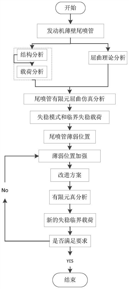
[0030] The invention is based on the buckling and instability failure of the tail nozzle in the engineering use, which affects the safety of the whole machine and the progress of model development. In harsh environment, based on finite element method theory and thin-walled cylinder buckling theory, a buckling-resistant design method for thin-walled tail nozzle is proposed.

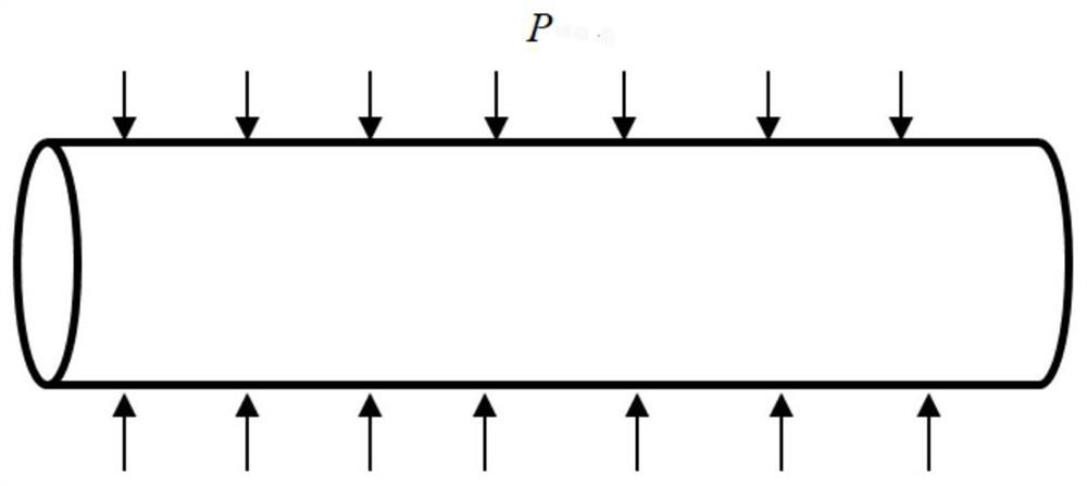
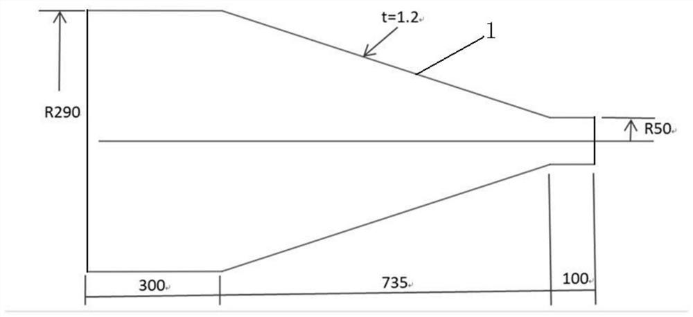
[0031] like figure 1 As shown, an embodiment of ...


PUM


Abstract

The invention belongs to the field of aero-engine structural design, and discloses an aero-engine thin-wall exhaust nozzle buckling resistance design method which comprises the following steps: S1, determining structural parameters and load of a thin-wall exhaust nozzle; s2, finite element buckling simulation analysis is conducted on the thin-wall exhaust nozzle, and a first-order critical instability load coefficient and a buckling instability vibration mode cloud picture are obtained; s3, based on a finite element buckling simulation analysis result, finding a maximum deformation position in the buckling instability vibration type cloud picture, and applying an annular mounting edge; and S4, finite element buckling simulation analysis is conducted on the thin-wall exhaust nozzle with the installation edge applied, a first-order critical instability load coefficient and a buckling instability vibration mode cloud picture are obtained and calculated, whether the first-order critical instability load coefficient meets the requirement or not is judged, if not, the steps S3-S4 are repeated, and if yes, the process is ended. The rigidity and stability of the thin-wall spray pipe can be effectively improved, the structural weight cannot be obviously increased, and meanwhile the overall appearance and pneumatic performance of the spray pipe cannot be affected.

Description

technical field [0001] The invention belongs to the field of aero-engine structure design, and in particular relates to an aero-engine thin-walled tail nozzle anti-buckling design method, which is used for guiding the structural design of aero-engine thin-walled components. Background technique [0002] As the heart of the aircraft, the aero-engine is known as the jewel in the crown of modern industry and the flower of industry. It is a high-speed rotating precision thermomechanical device. Modern aero-engines are pursuing a high thrust-to-weight ratio, and lightweight design has become an important consideration in structural design. There are a large number of thin-walled components in modern aero-engines. The tail nozzle is located at the rear end of the engine. For a military engine with a small bypass ratio, the tail nozzle is a complex adjustment mechanism device involving many types of components. It has relatively strong rigidity and is not prone to instability probl...

Claims


Application Information

Patent Timeline
IPC IPC(8): G06F30/15G06F30/23G06F111/04
CPCG06F30/15G06F30/23G06F2111/04
Inventor 郑晓霞韩耀昆李志强高姣姣杨桥
Owner TAIYUAN UNIV OF TECH
Why Eureka
Try Eureka