Calibration board, calibration method and calibration system

A calibration method and calibration board technology, applied in image analysis, instruments, calculations, etc., can solve problems such as calibration parameter errors, increase in total imaging distortion, imaging distortion, etc., to meet calibration requirements, improve calibration accuracy, and avoid uncertain variables Effect

Pending Publication Date: 2022-07-01
TRULY OPTO ELECTRONICS
View PDF1 Cites 0 Cited by
  • Summary
  • Abstract
  • Description
  • Claims
  • Application Information

AI Technical Summary

Problems solved by technology

[0007] When calibrating a telephoto camera, a teleconverter similar to that in the above-mentioned patent can also be used to change the focal length of the telephoto camera, but the teleconverter itself is also a kind of lens, and there is also the problem of imaging distortion. The teleconverter is equivalent to increasing the total distortion of the imaging, and will also introduce some uncertain variables, resulting in a large error in the calculated calibration parameters

Method used


Image

  • Calibration board, calibration method and calibration system
  • Calibration board, calibration method and calibration system
  • Calibration board, calibration method and calibration system

Examples


Embodiment 1

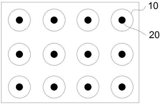
[0043] like figure 2 As shown, a calibration plate includes a two-dimensional plane on which a plurality of hollow calibration patterns 10 are distributed, and each hollow calibration pattern 10 is provided with a corresponding solid calibration pattern 20, wherein a plurality of The hollow calibration patterns 10 are distributed in M ​​rows and N columns on the two-dimensional plane, where M, N≥2.

[0044] The color of the hollow calibration pattern 10 and the corresponding solid calibration pattern 20 is not limited, and can be black; the hollow calibration pattern 10 is a hollow circle, the solid calibration pattern 20 is a solid circle, and the center of mass of each solid circle 20 corresponds to The center of the hollow circle 10.

Embodiment 2

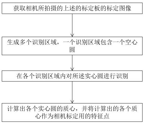
[0046] like image 3As shown, a calibration method includes the following steps:

[0047] S1: Acquire the calibration image of the calibration plate captured by the camera.

[0048] In this step S1, as figure 2 As shown, the calibration plate includes a two-dimensional plane on which a plurality of hollow calibration patterns 10 are distributed, and each hollow calibration pattern 10 is provided with a corresponding solid calibration pattern 20, wherein a plurality of hollow calibration patterns 10 are provided. The calibration patterns 10 are distributed in M ​​rows and N columns on the two-dimensional plane, where M and N≥2.

[0049] The color of the hollow calibration pattern 10 and the corresponding solid calibration pattern 20 is not limited, and can be black; the hollow calibration pattern 10 is a hollow circle, the solid calibration pattern 20 is a solid circle, and the center of mass of each solid circle 20 corresponds to The center of the hollow circle 10.

[005...

Embodiment 3

[0085] A calibration system, comprising a calibration board and a calibration device, the calibration board is used to communicate with a camera, so as to drive the camera to shoot at the calibration board, and receive a calibration image captured by the camera to perform embodiments The calibration method described in 2.

[0086] like figure 2 As shown, the calibration plate includes a two-dimensional plane on which a plurality of hollow calibration patterns 10 are distributed, and each hollow calibration pattern 10 is provided with a corresponding solid calibration pattern 20, wherein a plurality of hollow calibration patterns 10 are provided. The calibration patterns 10 are distributed in M ​​rows and N columns on the two-dimensional plane, where M and N≥2.

[0087] The color of the hollow calibration pattern 10 and the corresponding solid calibration pattern 20 is not limited, and can be black; the hollow calibration pattern 10 is a hollow circle, the solid calibration p...


PUM


Abstract

The invention discloses a calibration method, which comprises the following steps that a calibration image of a calibration plate shot by a camera is obtained, a plurality of hollow calibration patterns are distributed on the calibration plate, and a corresponding solid calibration pattern is arranged in each hollow calibration pattern; generating a plurality of identification areas, wherein one identification area comprises one hollow calibration pattern; identifying the solid calibration pattern in each identification area; and calculating the center of mass of each solid calibration pattern, and taking each calculated center of mass as a feature point for camera calibration. According to the calibration method, even if the calibration images shot by the camera are relatively fuzzy, the feature points in each calibration image can be accurately captured. The invention also discloses a calibration plate and a calibration system.

Description

technical field [0001] The invention relates to camera calibration technology, in particular to a calibration plate, a calibration method and a system. Background technique [0002] In the process of image measurement and machine vision applications, in order to determine the relationship between the three-dimensional geometric position of a point on the surface of a space object and its corresponding point in the image, a geometric model of camera imaging must be established. These geometric model parameters are the calibration parameters of the camera. , and the process of solving these calibration parameters is called camera calibration. The calibration parameters of the camera generally include internal parameters, external parameters and distortion parameters. [0003] There are two purposes for calibrating the camera. One is that the degree of distortion of each camera is different. Through the calibration, the original image can be corrected and restored by using the...

Claims


Application Information

Patent Timeline
IPC IPC(8): G06T7/80G06T7/66
CPCG06T7/80G06T7/66
Inventor 林挺
Owner TRULY OPTO ELECTRONICS
Why Eureka
Try Eureka