Electric connector

A technology for electrical connectors and contact parts, applied in the direction of connection, fixed connection, circuits, etc., can solve the problems of short-time charging, large current flowing in electrical connectors, and increased current, so as to reduce conductor resistance, increase strength, and reduce metal volume. increased effect

Pending Publication Date: 2022-07-01
HIROSE ELECTRIC GROUP
View PDF1 Cites 0 Cited by
  • Summary
  • Abstract
  • Description
  • Claims
  • Application Information

AI Technical Summary

Problems solved by technology

However, with the high functionality of these electronic devices, the current used for these electronic devices tends to increase.
In addition, these electronic devices usually use rechargeable batteries as power sources, and there are also requirements for short-term charging, and there are cases where large currents flow through small electrical connectors.

Method used


Image

  • Electric connector
  • Electric connector
  • Electric connector

Examples


Embodiment approach 1

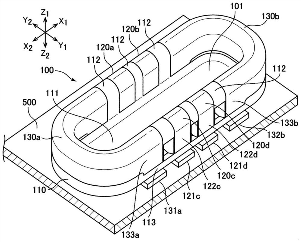
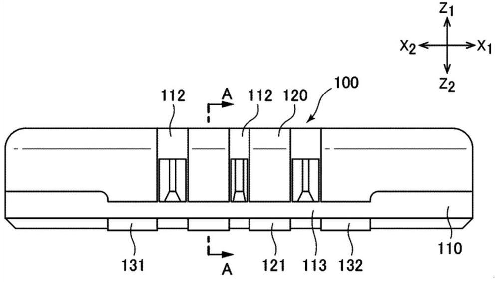
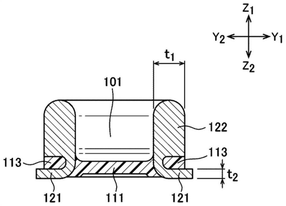
[0042] figure 1 It is a perspective view showing the structure of an electrical connector (plug connector) according to Embodiment 1 of the present invention, figure 2 is the main view, image 3 Yes figure 2 A cross-sectional view of the A-A section. Figure 4 is expressed in figure 1 A perspective view of an electrical connector with only the terminals removed with the housing portion. Figure 5 It is a perspective view which shows the structure of a 1st terminal. Image 6 is to indicate Figure 5 Side view of the structure of the terminal shown. Figure 7 It is a perspective view which shows the structure of a 2nd terminal. Figure 8 is to indicate Figure 7 Side view of the structure of the terminal shown.

[0043] First, according to Figure 1 to Figure 4, the structure of the electrical connector of the first embodiment will be described. The electrical connector according to the first embodiment is a plug connector 100 mounted on a substrate 500 such as a pr...

Embodiment approach 2

[0063] Figure 15 It is a perspective view showing the structure of an electrical connector (plug connector) according to Embodiment 2 of the present invention, Figure 16 is the main view, Figure 17 Yes Figure 16 A cross-sectional view of the B-B section.

[0064] Compared with the above-described first embodiment, the second embodiment of the present invention does not have a recessed portion filled with a part of the housing 210 between the contact portion and the mounting portion of the terminals 220 and 230 . Instead, a part of the housing (the terminal fixing part 213 ) is in close contact with and covers the fitting direction (Z 1 direction) surface. The configuration of the other parts is the same as that of the above-described first embodiment, and therefore, overlapping descriptions are omitted.

[0065]The electrical connector according to the second embodiment is a plug connector 200 mounted on a substrate 500 such as a printed circuit board, and includes an...

Embodiment approach 3

[0069] Figure 18 It is a perspective view which shows the structure of the electrical connector (receptacle connector) which concerns on Embodiment 3 of this invention. Figure 19 It is a perspective view which shows the structure of only a terminal except a case part.

[0070] Figure 20 is a perspective view showing the structure of the terminal, Figure 21 is a side view. Figure 20 and Figure 21 The terminals are used as reinforcing metal parts. In the third embodiment, the present invention is applied to a receptacle connector. Parts other than the terminals 330 (reinforcing metal pieces) are the same as those of a general receptacle connector.

[0071] The electrical connector of the third embodiment is a receptacle connector 300 mounted on a substrate 500 such as a printed circuit board, and includes an insulating housing 310 , four conductive first terminals 320 fixed to the housing 310 , and four conductive first terminals 320 . The conductive second terminal...


PUM


Abstract

Provided is an electrical connector which satisfies the requirements for lightness, thinness, shortness and miniaturization of an electronic device, suppresses the resistance of a conductive terminal to be low, and can cope with an increase in the current flowing through the conductive terminal. An electrical connector such as a plug connector (100) is provided with an insulating housing (110) and a conductive terminal (120, 130) fixed to the housing (110), the terminal (120, 130) including a mounting portion (121, 131, 132) connected to a substrate (500) and a contact portion (122, 133) protruding from the mounting portion (121, 131, 132) in a fitting direction (Z1 direction), and the plate thickness (t1) of the contact portion (122, 133) is greater than the plate thickness (t2) of the mounting portion (121, 131, 132) in a direction (Z1Z2 direction) orthogonal to the substrate (500).

Description

technical field [0001] The present invention relates to an electrical connector, and more particularly, to an electrical connector mounted on a substrate. Background technique [0002] Conventionally, a board-to-board type electrical connector has been used as a connector for connecting the surfaces of the boards to each other. In the board-to-board type electrical connector, the plug connector and the receptacle connector are grouped together, and the plug connector is inserted into the receptacle connector to make electrical connection between the conductive terminals (contacts) of each other, thereby forming an electrical connection. As a technique related to such a board-to-board type electrical connector, for example, the technique described in Patent Document 1 (Japanese Patent Laid-Open No. 2017-16897 ) and the like can be mentioned. [0003] Patent Document 1: Japanese Patent Laid-Open No. 2017-16897 [0004] In recent years, with the demand for reduction in thickn...

Claims


Application Information

Patent Timeline
Patent Type & Authority Applications(China)
IPC IPC(8): H01R13/04H01R13/10H01R12/57
CPCH01R13/04H01R13/10H01R12/57H01R12/716H01R12/73H01R43/205H01R12/707
Inventor 小林勇贵
Owner HIROSE ELECTRIC GROUP
Why Eureka
Try Eureka