
Terminal assembly of electric connector and electric connector structure

A technology of electrical connectors and terminal assemblies, which is applied in the direction of connection, contact parts, fixed/insulated contact members, etc., can solve the problems of reducing signal integrity, impedance discontinuity, and negative impact on complete signal transmission, so as to improve energy transmission Loss issues, reducing stub effect, and improving the effect of transmission bandwidth and rate

Pending Publication Date: 2022-07-01
IND TECH RES INST
View PDF0 Cites 0 Cited by
  • Summary
  • Abstract
  • Description
  • Claims
  • Application Information

AI Technical Summary

Problems solved by technology

In addition, if the conductor transmitting the high-frequency electronic signal itself has an unclosed (that is, open) terminal, the impedance discontinuity of the unclosed terminal will occur, thereby reducing the signal integrity of the high-frequency signal transmission path, which is generally called residual. Stub effect
[0004] The problem of the stub effect of the existing high-speed connectors is partly caused by the mutual mating of the male and female connector structures. In order to ensure that the contact between the two connectors is stable, there must be scratches between the mated male and female connector terminals. phenomenon (wiping), when two matched connectors exchange high-frequency electronic signals with each other, the unavoidable scratches cause the terminals to have unclosed terminals, resulting in stub effects to reduce the integrity of high-frequency signal transmission, Easily negatively impact signal integrity due to stub effects

Method used


Image

  • Terminal assembly of electric connector and electric connector structure
  • Terminal assembly of electric connector and electric connector structure
  • Terminal assembly of electric connector and electric connector structure

Examples


Embodiment Construction

[0071] In order to make the objectives, technical solutions and advantages of the present invention more clearly understood, the present invention will be further described in detail below in conjunction with specific embodiments and with reference to the accompanying drawings.

[0072] The following examples are only used to illustrate the technical solutions of the present invention more clearly, but cannot limit the protection scope of the present invention.

[0073] It should be noted that, in the description of each embodiment, the so-called "first", "second", "third", and "fourth" are used to describe different components, and these components are not modifiers are restricted. In addition, for the convenience and clarity of description, the thickness or size of each component in the drawings is shown in an exaggerated or omitted or rough manner for those skilled in the art to understand and read, and the size of each component is not completely the same The actual size is...


PUM


Abstract

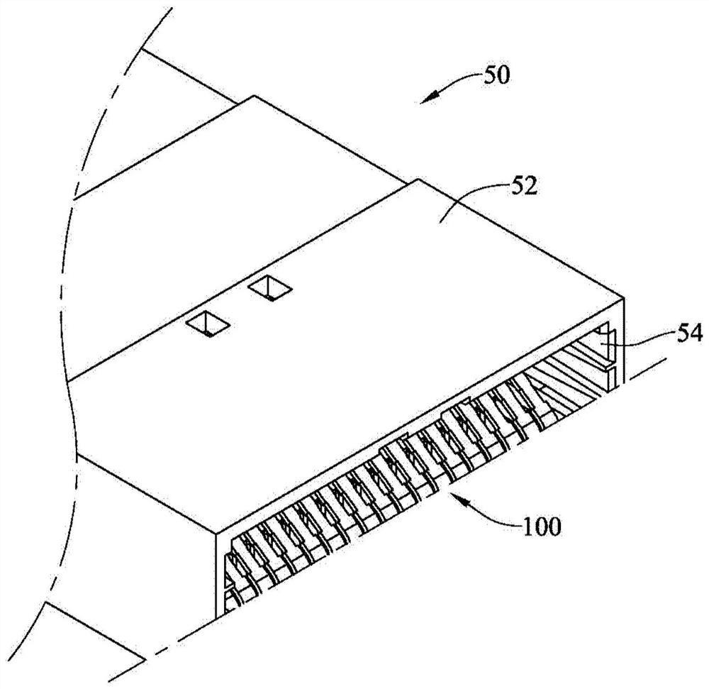
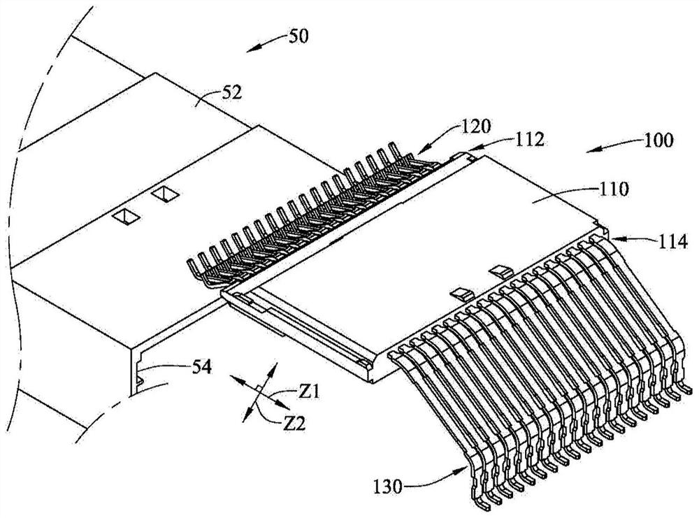
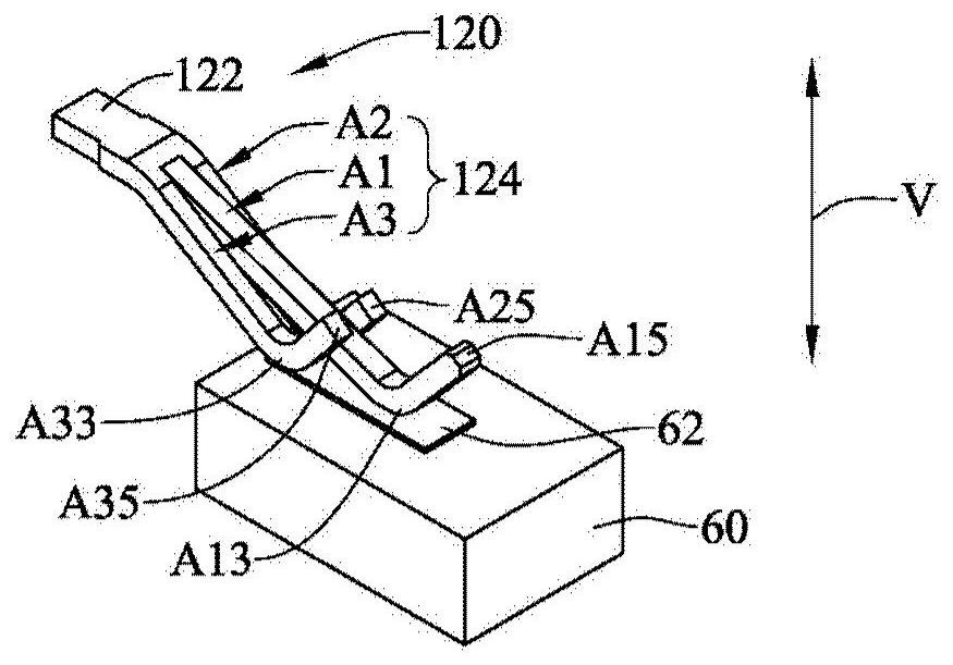
An electric connector structure comprises an insulating shell and at least one terminal assembly. The terminal assembly comprises an insulating body and a plurality of terminals. The terminals penetrate through the insulating body. The terminal comprises a terminal body and at least two cantilever sections. Each cantilever section is connected with the terminal body, and the cantilever sections extend to form corresponding contact parts in the length direction of the terminal body. The contact parts are in contact with corresponding signal contacts on the electronic card, and the contact parts are in contact with different positions of the signal contacts. In addition, the invention also provides a terminal assembly of the electric connector.

Description

technical field [0001] The present invention relates to a terminal assembly of an electrical connector and an electrical connector structure. Background technique [0002] Signals in various electronic devices are mainly transmitted to each other through a plurality of electronic connectors. Generally speaking, an electronic connector is mainly composed of an insulating shell and a plurality of metal terminals. With the development of science and technology, the amount of information to be transmitted by electronic devices is increasing, so it is necessary to increase the transmission frequency or speed of the signal. [0003] Due to the higher transmission frequency or rate of electronic connectors, the energy of high-frequency signals is also prone to loss during transmission, which includes conductor loss and dielectric loss. In addition, if the conductor that transmits high-frequency electronic signals has an unclosed (ie, open) terminal, the unclosed terminal will have...

Claims


Application Information

Patent Timeline
Patent Type & Authority Applications(China)
IPC IPC(8): H01R13/40H01R13/02H01R12/70
CPCH01R13/40H01R13/02H01R12/70
Inventor 黄添富
Owner IND TECH RES INST
Learn More