Bottle blowing method

A bottle blowing machine and preform technology, which is applied to household appliances, other household appliances, household components, etc., can solve the problems of voltage fluctuation, space congestion, waste of manpower and material resources, etc., and achieve the effect of stable clamping and good support.

Inactive Publication Date: 2022-07-05
广东海文胜唐塑料制品有限公司
View PDF0 Cites 0 Cited by
  • Summary
  • Abstract
  • Description
  • Claims
  • Application Information

AI Technical Summary

Problems solved by technology

[0004] 1. In the working process of the blow molding machine in the prior art, the position of the bottle mouth is not blown, so the clamp on the transmission line clamps the position of the bottle mouth to move; at the same time, the blow molding mouth is also selected at the bottle mouth position, This has led to the concentration of the conveyor line and blow molding equipment on the side of the bottle mouth, resulting in serious space congestion
[0005] 2. In the blow molding machine of the prior art, the clamp on the transmission line clamps the position of the bottle mouth to move. If other parts are clamped, the expansion and clamping of the blow molding are contradictory. Therefore, the clamping device cannot be used to clamp bottom of bottle
[0006] 3. The driving device in the prior art cannot achieve multi-stage displacement as a whole without intelligent stroke control, and can only realize one-stage displacement
[0007] 4. In the blow molding process of the prior art, common abnormalities include debris being blown into blow molding equipment or PET bottles, which can only be checked and cleaned later, which wastes a lot of manpower and material resources
[0008] 5. The piston in the prior art can only realize the two-way driving function, but cannot realize the supporting function
[0009] 6. The pistons of the prior art cannot realize the organic combination of individual motion and common motion when multi-piston linkage is performed
[0010] 7. The blowing process operation of the prior art is to preheat and then pass the cooling water, but it will cause voltage fluctuations
[0011] 8. In the prior art, there may be holes in the conveyor belt, but these holes are not further used to achieve more functions

Method used


Image

  • Bottle blowing method
  • Bottle blowing method
  • Bottle blowing method

Examples


Embodiment Construction

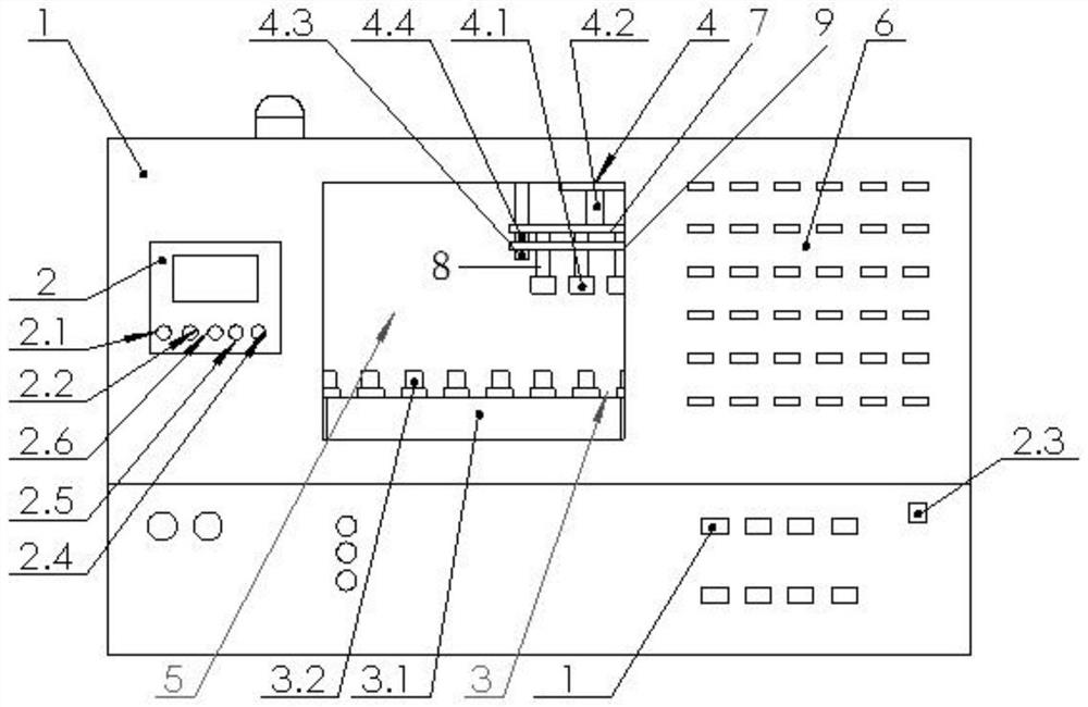
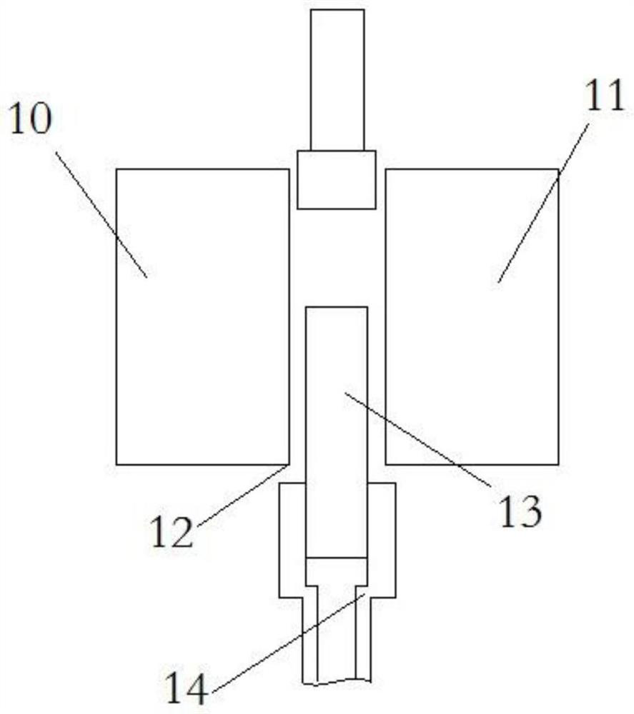
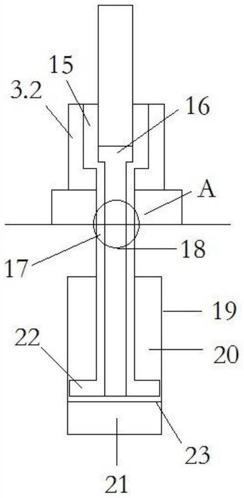
[0052] As shown in the figure: a bottle blowing method, which uses a bottle blowing machine to work. The bottle blowing machine includes a body, and the body is provided with a control module, a transmission module, a blow molding module, a heating cavity, a left mold, a right mold, and a stroke. A control device, a cooling cavity, and a heating device; the heating device is provided in the left mold and the right mold, and the control module controls the operation of the conveying module and the blowing module; the conveying module includes a conveying belt, and the conveying belt is provided with a lower Clamp; the blow molding module includes an upper frame, an upper clamp, a main rod, a three-way valve, a lower frame, a sub-rod, a wiring frame, a slide plate, and a four-way joint; the stroke control device includes a connecting part, an inner bush, a piston head , a piston rod, a lifting rod, a hydraulic cylinder, and a piston plate; the method includes the following steps:...


PUM


Abstract

According to the bottle blowing method, a bottle blowing machine is used for working, and the method comprises the following steps that after a main power switch is turned on, cooling water is introduced into a cooling cavity; turning on the low-pressure gas source switch for 30 seconds and then turning off the low-pressure gas source switch; starting the heating device for preheating; a bottle blank discharging operation is carried out, the conveying belt is controlled to start conveying, a high-pressure air source switch is turned on to carry out blow molding on the bottle blank, and the bottle blank enters the cooling cavity after blow molding; after bottle blowing is finished, the high-pressure air source switch and the heating device are turned off, the conveyor belt is controlled to stop moving, and finally the main power supply is turned off.

Description

technical field [0001] The invention relates to the technical field of bottle blowing machine devices, in particular to a bottle blowing method. Background technique [0002] PET bottles have strong applicability and are widely used in daily necessities, daily chemical packaging and other fields. After the existing bottle blowing machine equipment controls the temperature and pressure within an effective range, the raw materials are added to the mold, and the raw materials are processed to complete the production of preforms, so that the preforms can be processed at a specific temperature and pressure. Improve the quality of preforms, facilitate the processing of preforms, improve the quality of finished plastic bottles, and reduce the scrap rate of finished plastic bottles. [0003] In actual production practice, there are the following problems: [0004] 1. In the working engineering of the bottle blowing machine in the prior art, the position of the bottle mouth is not ...

Claims


Application Information

Patent Timeline
Patent Type & Authority Applications(China)
IPC IPC(8): B29C49/42B29C49/28B29C49/48B29C49/56B29C49/58B29C49/64B29C49/78B29L31/00
CPCB29C49/4205B29C49/28B29C49/42B29C49/56B29C49/58B29C49/64B29C49/48B29C49/78B29L2031/7158
Inventor 曾巧文苏海涛张燕毛自慧
Owner 广东海文胜唐塑料制品有限公司
Why Eureka
Try Eureka