[0035] The technical solutions in the embodiments of the present invention will be clearly and completely described below with reference to the accompanying drawings in the embodiments of the present invention. Obviously, the described embodiments are only a part of the embodiments of the present invention, rather than all the embodiments; based on the The embodiments of the present invention, and all other embodiments obtained by those of ordinary skill in the art without creative work, fall within the protection scope of the present invention.
[0036] In the description of the present invention, it should be understood that the terms "upper", "lower", "front", "rear", "left", "right", "top", "bottom", "inside", " “Outside” and other indications of orientation or positional relationship are based on the orientation or positional relationship shown in the accompanying drawings, which are only for the convenience of describing the present invention and simplifying the description, rather than indicating or implying that the referred device or element must have a specific orientation, a specific orientation, and a specific orientation. The orientation configuration and operation of the device should not be construed as a limitation of the present invention.
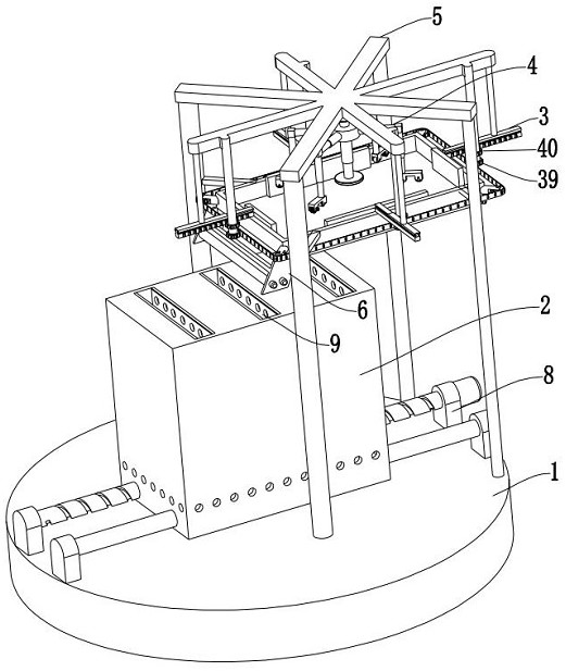
[0037] like figure 1 As shown in the figure, the present invention provides a non-input self-commutating drying type secretarial data organizer, including a stable chassis 1, a non-input self-commutating drying storage mechanism 2, a self-centering supporting mechanism 3, and a flexible buffer type rolling smoothing Mechanism 4, launch-type support mechanism 5 and limit transmission mechanism 6, the non-input type self-commutation drying and storage mechanism 2 is set on the upper wall of the stable chassis 1, and the launch-type support mechanism 5 is set on the stable chassis 1, self-centering support The mechanism 3 is provided on the launch-type support mechanism 5 , the flexible buffer type rolling and smoothing mechanism 4 is provided on the launch-type support mechanism 5 , and the limit transmission mechanism 6 is provided on the self-centering support mechanism 3 .
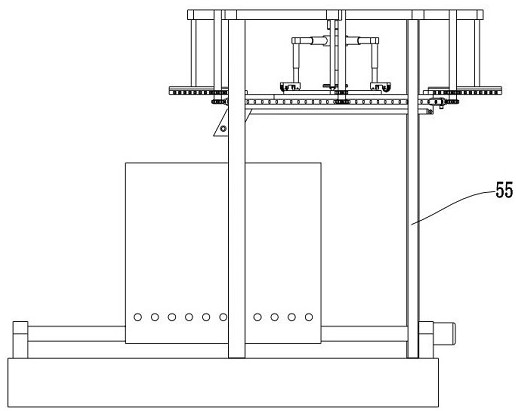
[0038] like figure 1 , image 3 , Figure 4 , Figure 10 As shown, the launch-type support mechanism 5 includes a rice-shaped support plate 54, a support column 55, a support plate 56 and an engaging chute 57. The support column 55 is arranged on the stable chassis 1, and the rice-shaped support plate 54 is arranged on the support column 55. The support plate 56 is arranged on the support column 55 , the engaging chute 57 is arranged on the support column 55 , and the T-shaped protrusion 44 is engaged and slid in the engaging chute 57 .
[0039] like figure 1 , Figure 9 As shown, the flexible buffer type rolling and smoothing mechanism 4 includes a direction adjusting motor 19, a fixed disc 20, a horizontal telescopic piece 21, a longitudinal telescopic piece 22, a flexible buffer type hot pressing smoothing device 23 and a fixed pressing device 24. The motor 19 is arranged on the launch-type support mechanism 5, the fixed plate 20 is connected with the output end of the steering motor 19, the horizontal telescopic piece 21 is arranged on the fixed plate 20, the longitudinal telescopic piece 22 is connected with the movable end of the horizontal telescopic piece 21, and the flexible The buffer type hot pressing smoothing device 23 is connected to the movable end of the longitudinal telescopic member 22; the flexible buffer type hot pressing smoothing device 23 includes a fixed frame 25, a forward flexible buffer type flattening impeller 26, a flattening driving member 27 and a heat roller Press the leveling wheel 28, the fixing frame 25 is connected with the movable end of the longitudinal telescopic piece 22, the clockwise flexible buffer type flattening impeller 26 is rotated and installed on the fixing frame 25, the flattening driving member 27 is arranged on the fixing frame 25, and the heat roller The pressing and leveling wheel 28 is rotatably arranged on the fixing frame 25, and the leveling driving member 27 includes a leveling fixing member 29 and a leveling motor 30. The leveling fixing member 29 is arranged on the fixing frame 25, and the leveling motor 30 is arranged on the levelling motor 30. On the fixed frame 25, the output end of the leveling motor 30 is connected with the forward flexible buffer type leveling impeller 26; the fixed pressing device 24 includes a pressing rod 31 and a pressing plate 32, and the pressing rod 31 is arranged at the bottom of the fixed plate 20. On the wall, a pressing plate 32 is arranged on the movable end of the pressing rod 31 .
[0040] like figure 1 , Figure 5 , Figure 11 , Figure 12 As shown, the self-centering supporting mechanism 3 includes a supporting frame 33, a supporting sliding device 34 and a centering positioning device 35. The supporting frame 33 is provided on the launch-type supporting mechanism 5, and the supporting sliding device 34 is provided on the supporting frame 33. On the bottom wall, the central positioning device 35 is arranged on the supporting frame 33 and the launch-type supporting mechanism 5; The strip 41, the centering push plate 42 and the centering motor 43, the support member 36 is arranged at the four corners of the outer side of the support frame 33, the transmission pulley 37 is rotated and arranged on the support member 36, the transmission belt 38 is sleeved on the transmission pulley 37, and the center rack 41 is provided with a T-shaped protrusion 44, the T-shaped protrusion 44 is snapped and slid on the launch-type support mechanism 5, the center push plate is connected with the center rack 41, and the center drive wheel 40 is rotated and arranged on the launch-type support mechanism 5. , the center drive wheel 39 is connected with the center drive wheel 40, the center drive wheel 39 is meshed and connected with the drive belt 38, the center motor 43 is arranged on the support 36, and the output end of the center motor 43 is connected with the drive pulley 37; The supporting sliding device 34 includes The supporting lower sliding plate 45, the supporting sliding fixing member 46 and the supporting sliding motor 47 are supported. , the supporting sliding motor 47 is arranged on the supporting sliding fixing member 46 , and the output end of the supporting sliding motor 47 is connected with the supporting lower sliding plate 45 .
[0041] like figure 1 , Figure 13 As shown, the limit transmission mechanism 6 includes a transmission fixing plate 48, a paper limiting plate 49, a transmission roller 50, a transmission roller 2 51, a transmission motor 1 52 and a transmission motor 2 53, and the transmission fixing plate 48 is provided on the support frame 33. On the outer side wall, the paper limiting plate 49 is arranged on the transmission fixing plate 48, the first transmission roller 50 is arranged on the transmission fixing plate 48, the second transmission roller 51 is arranged on the transmission fixing plate 48, and the first transmission motor 52 is arranged on the transmission fixing plate 48. On the fixed plate 48, the transmission motor two 53 is arranged on the transmission fixed plate 48, the output end of the transmission motor one 52 is connected with the transmission roller one 50, the output end of the transmission motor two 53 is connected with the transmission roller two 51, and the transmission motor one 52 and The direction of the transmission motor two 53 is reversed.
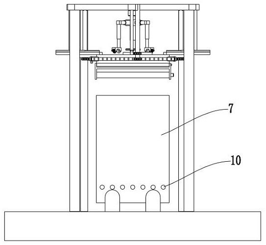
[0042] like figure 1 , figure 2 , Figure 7 , Figure 8 As shown, the non-input type self-commutating drying storage mechanism 2 includes a porous data storage frame 7, a storage frame moving device 8 and a non-input self-commutating drying device 9. The storage frame moving device 8 is arranged on the upper wall of the stable chassis 1. , the porous data storage frame 7 is arranged on the storage frame moving device 8, the porous data storage frame 7 is provided with ventilation holes 10, and the non-input type self-commutating drying device 9 is arranged in the porous data storage frame 7; no input The type self-commutating drying device 9 includes a non-uniform magnetic field setting member 11, a data storage partition 12, a data supporting bottom plate 13, a blocking bottom plate 14 and a heating pipe 15. The non-uniform magnetic field setting member 11 is provided in the porous data storage frame 7. Inside, the data storage partition 12 is arranged in the perforated data storage frame 7, the data supporting bottom plate 13 is arranged in the perforated data storage frame 7 and is arranged on the data storage partition 12, and the blocking bottom plate 14 is arranged in the data storage partition. On the bottom wall of the plate 12, a heating tube 15 is arranged on the data storage partition 12, and the heating tube 15 is arranged between the data supporting bottom plate 13 and the blocking bottom plate 14; the non-uniform magnetic field setting member 11 includes a plate magnet 16 and a concave-convex magnet 17. The plate magnet 16 is arranged in the aperture type data storage frame 7, the concave and convex magnet 17 is arranged in the aperture type data storage frame 7, and the data storage partition 12 is arranged between the plate magnet 16 and the concave and convex magnet 17; The plate 12, the data supporting bottom plate 13 and the blocking bottom plate 14 are provided with ventilation holes 18; the storage frame moving device 8 includes a fixing member 58, a limit post 59, a moving screw 60 and a moving motor 61, and the fixing member 58 is arranged on the stable chassis 1. On the upper wall, the limiting column 59 is arranged on the fixing member 58, the moving screw 60 is rotatably arranged on the fixing member 58, the moving motor 61 is arranged on the fixing member 58, and the output end of the moving motor 61 is connected with the moving screw 60.
[0043]In specific use, the user puts the paper to be sorted on the lower support slide 45, starts the centering motor 43, the centering motor 43 rotates to drive the drive pulley 37 to rotate, the drive pulley 37 rotates to drive the drive belt 38 to rotate, and the drive belt 38 rotates to drive the centering drive pulley 39 rotates, the center drive wheel 39 rotates to drive the center drive wheel 40 to rotate, the center drive wheel 40 rotates to drive the center rack 41 to rotate, the center rack 41 rotates to drive the center push plate 42 to move, and the push plate moves to center the paper, thereby realizing the For the technical effect of centering, after the centering is completed, the pressing rod 31 is activated, and the pressing rod 31 is extended to drive the pressing plate 32 to move down until the pressing plate 32 presses the paper, and then the direction adjustment motor 19 is activated, and the direction adjustment motor 19 The rotation drives the fixed plate 20 to rotate, and the rotation of the fixed plate 20 realizes the technical effect of adjusting the leveling angle, and then perfectly adapts to different sizes of paper. After the angle adjustment is completed, the longitudinal expansion member 22 is activated, and the longitudinal expansion member 22 is extended to drive the fixed plate. The frame 25 moves down, and the fixed frame 25 moves down to drive the forward flexible buffer type flattening impeller 26 and the hot rolling smoothing wheel 28 to move down until the hot rolling smoothing wheel 28 presses the paper, and the flattening motor 30 is started. The rotation of the flattening motor 30 drives the forward flexible buffering flattening impeller 26 to rotate, so that the edges and corners of the curled and folded paper are flattened in a flexible buffering type, and at the same time, the hot-rolled flattening wheel 28 is followed by the flattening of the edges and corners. Hot rolling, thereby achieving the technical effect of completely leveling the curled corners, effectively solving the traditional technical problem of damage to the corners caused by rigid scraping of the corners, start the supporting sliding motor 47, and the supporting sliding motor 47 rotates The lower support slide 45 is driven to rotate, and then the paper falls into the limit transmission mechanism 6 along the support lower slide 45, and the first transmission motor 52 and the second transmission motor 53 are activated. The rotation of the second motor 53 drives the second transmission roller 51 to rotate, and then the paper is transmitted between the data storage partitions 12 , and the moving motor 61 is activated. At the same time, due to the uneven arrangement of the plate magnets 16 and the concave and convex magnets 17, an uneven magnetic field is generated between the plate magnets 16 and the concave and convex magnets 17, thereby inhaling the paramagnetic gas Between the plate magnet 16 and the concave-convex magnet 17, the magnetism of the gas heated by the electric heating tube is weakened, and then the heated gas is squeezed by the paramagnetic gas that enters later to flow upward and discharge, and the continuous flow of air is used to realize the ventilation of secret materials. The technical effect of continuous drying can effectively prevent the material from being damaged by moisture. The above is the specific work flow of the present invention, and this step can be repeated next time.
[0044] It should be noted that, in this document, relational terms such as first and second are only used to distinguish one entity or operation from another entity or operation, and do not necessarily require or imply any relationship between these entities or operations. any such actual relationship or sequence exists. Moreover, the terms "comprising", "comprising" or any other variation thereof are intended to encompass non-exclusive inclusion such that a process, method, article or device comprising a list of elements includes not only those elements, but also includes not explicitly listed or other elements inherent to such a process, method, article or apparatus.
[0045] Although embodiments of the present invention have been shown and described, it will be understood by those skilled in the art that various changes, modifications, and substitutions can be made in these embodiments without departing from the principle and spirit of the invention and modifications, the scope of the present invention is defined by the appended claims and their equivalents.
[0046] The present invention and its embodiments have been described above, and the description is not restrictive, and what is shown in the accompanying drawings is only one of the embodiments of the present invention, and the actual structure is not limited thereto. All in all, if those of ordinary skill in the art are inspired by it, and without departing from the purpose of the present invention, any structural modes and embodiments similar to this technical solution are designed without creativity, and all should belong to the protection scope of the present invention.