Interior decoration device for denial vehicle
An interior decoration and anti-vehicle technology, which is applied in the field of automobile interior decoration, can solve the problems of monotonous display effects of decorations, and achieve the effects of improving convenience, reducing costs, and facilitating installation and disassembly
- Summary
- Abstract
- Description
- Claims
- Application Information
AI Technical Summary
Problems solved by technology
Method used
Image
Examples
Embodiment 1
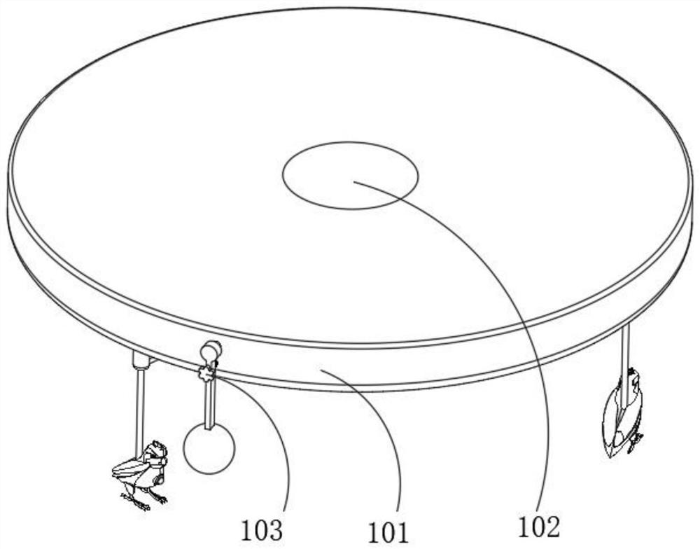
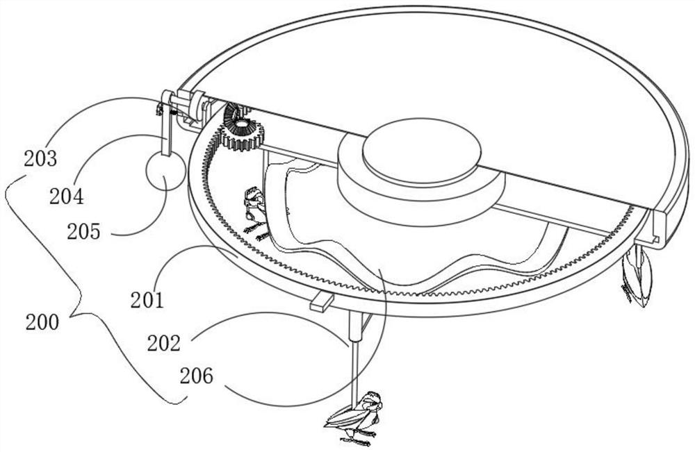
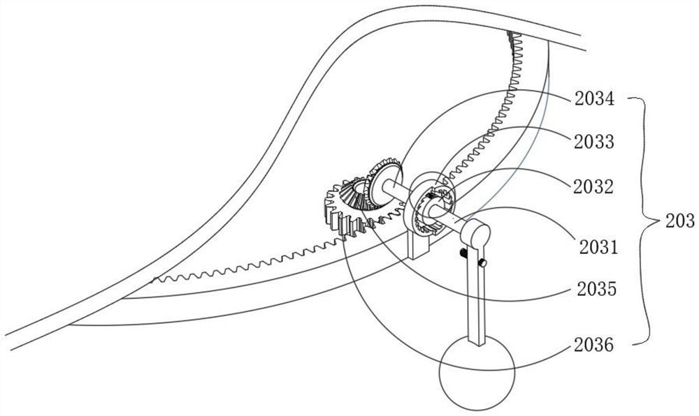
[0034] combine figure 1 As shown in FIG. 7, the present invention provides a vehicle interior decoration device for rejecting a vehicle, which includes a casing 101 and a load box 102 arranged in the casing 101. The casing 101 is provided with a display mechanism for improving the viewing degree by means of circular displacement. 200, a positioning mechanism 300 is provided between the outer casing 101 and the load box 102 for connecting the outer casing 101 and the load box 102 by means of a snap connection. A rocker 204 is provided on one side, a counterweight 205 is fixed at the bottom of the rocker 204, a drive assembly 203 for driving the inner gear ring 201 to rotate is provided in the housing 101, and a decoration component for decoration is provided at the bottom of the inner gear ring 201 202, the bottom of the housing 101 is provided with an elastic component 206 that drives the decorative component 202 to move up and down by elastic force. During the driving process...
Embodiment 2
[0040] combine Figure 8 and 9 As shown, on the basis of the first embodiment, the positioning mechanism 300 includes a positioning ring 301 fixed in the casing 101 , the inner side wall of the positioning ring 301 is provided with a plurality of slots 306 , and the outer side of the load box 102 is provided with a plurality of cavities, A second spring 302 is fixedly connected in the cavity, an end of the second spring 302 is fixed with a clamping block 303, the end of the clamping block 303 extends into the corresponding clamping slot 306, and a pull rod 305 is slidably connected to the bottom of the load box 102. A chain 304 is hinged between the clamping block 303 and the pull rod 305. First, the load box 102 is installed on the top of the vehicle. Since the positioning ring 301 is connected to the housing 101, the second spring 302 pushes the clamping block 303 so that its end is inserted into the positioning ring 301. Then, the connection of the device can be completed ...
PUM
 Abstract
Description
Claims
Application Information
 - R&D
- Intellectual Property
- Life Sciences
- Materials
- Tech Scout
- Unparalleled Data Quality
- Higher Quality Content
- 60% Fewer Hallucinations
Browse by: Latest US Patents, China's latest patents, Technical Efficacy Thesaurus, Application Domain, Technology Topic, Popular Technical Reports.
© 2025 PatSnap. All rights reserved.Legal|Privacy policy|Modern Slavery Act Transparency Statement|Sitemap|About US| Contact US: help@patsnap.com


