Intelligent ventilation structure of wind driven generator
A generator set, smart technology, applied in the direction of wind engine, wind motor combination, wind engine control, etc., can solve the problems of low ventilation efficiency, untimely heat dissipation, and affecting the safety performance of the device, so as to increase battery life and improve ventilation efficiency , Increase the effect of ventilation efficiency
- Summary
- Abstract
- Description
- Claims
- Application Information
AI Technical Summary
Problems solved by technology
Method used
Image

Examples
Embodiment 1
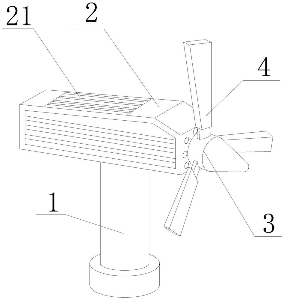
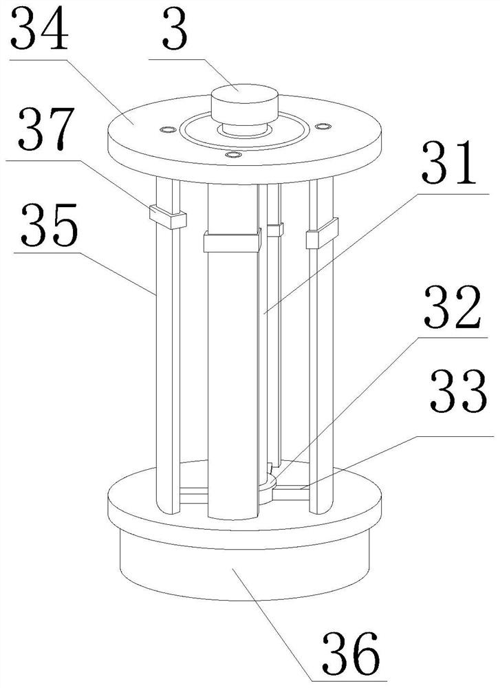
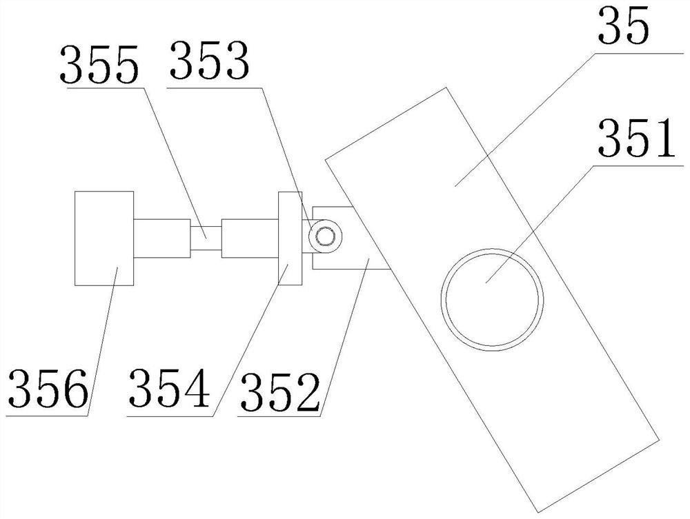
[0033] like Figure 1-7 As shown, the present invention provides an intelligent ventilation structure for wind turbines, including a wind pole 1, a generator set 2, a rotating set 3 and a rotating blade 4, the top of the wind pole 1 is fixedly installed with a generator set 2, and the outer side of the generator set 2 A heat dissipation hole 21 is provided, one end of the generator set 2 is fixedly connected with a rotating group 3, a rotating blade 4 is fixedly installed on the outer side of the rotating group 3, and a fixed shaft column 31 is fixedly connected to the side of the rotating group 3 close to the generator set 2, and the fixed shaft The top of the column 31 is provided with a ventilation protection plate 34, the bottom of the ventilation protection plate 34 is fixedly connected with a fixing rod 351, the outer side of the fixing rod 351 is movably installed with a ventilation plate 35, and one side of the bottom of the ventilation plate 35 is fixedly connected wit...
Embodiment 2
[0036] like Figure 1-7As shown, on the basis of Embodiment 1, the present invention provides a technical solution: preferably, a movable block 32 is movably installed on the outer bottom of the fixed shaft column 31, and a connecting rod 33 is fixedly connected to the outer side of the movable block 32, and the connecting rod 33 A cleaning block 321 is fixedly installed on the side away from the movable block 32, the side surface of the cleaning block 321 is arranged on the inner side of the ventilation plate 35, the outer surface of the fixed shaft column 31 is provided with a moving groove 310, and a sliding groove 310 is fixedly installed inside the moving groove 310. A limit block 312 is fixedly installed on one end of the column 311 and the sliding column 311, a telescopic rod 313 is fixedly installed on the side of the limit block 312, and a push block 314 is fixedly connected to the other end of the telescopic rod 313. The inner movable sleeve of the push block 314 Con...
Embodiment 3
[0039] like Figure 1-7 As shown, on the basis of Embodiment 1, the present invention provides a technical solution: preferably, a fixing base 36 is fixedly installed at the bottom of the fixing rod 351, a fixing hole 361 is opened inside the fixing base 36, and the inside of the fixing hole 361 is It is arranged on the outer side of the bottom of the fixing rod 351, the inner side of the fixing hole 361 is provided with a clamping block 362, the side surface of the clamping block 362 is arranged on the outer side of the fixing rod 351, and the outer surface of the fixing rod 351 is fixedly installed with a friction pad 364, which is clamped. One end of the block 362 away from the fixing rod 351 is fixedly installed with a hydraulic column 363 , and the side surface of the hydraulic column 363 is fixedly installed inside the fixed base 36 .
[0040] In this embodiment, the fixing rod 351 is inserted inside the fixing hole 361, and the hydraulic column 363 is driven by electric...
PUM
 Abstract
Description
Claims
Application Information
 - R&D
- Intellectual Property
- Life Sciences
- Materials
- Tech Scout
- Unparalleled Data Quality
- Higher Quality Content
- 60% Fewer Hallucinations
Browse by: Latest US Patents, China's latest patents, Technical Efficacy Thesaurus, Application Domain, Technology Topic, Popular Technical Reports.
© 2025 PatSnap. All rights reserved.Legal|Privacy policy|Modern Slavery Act Transparency Statement|Sitemap|About US| Contact US: help@patsnap.com