
Control method and control device of synchronizer lubricating system and synchronizer lubricating system

A technology of lubricating system and control method, applied in gear lubrication/cooling, clutch, mechanical drive clutch, etc., can solve the problems of inability to achieve precise control of lubricating oil amount, uncontrollable lubricating oil amount, poor lubricating effect, etc.

Pending Publication Date: 2022-07-05
CHINA FIRST AUTOMOBILE
View PDF0 Cites 0 Cited by
  • Summary
  • Abstract
  • Description
  • Claims
  • Application Information

AI Technical Summary

Problems solved by technology

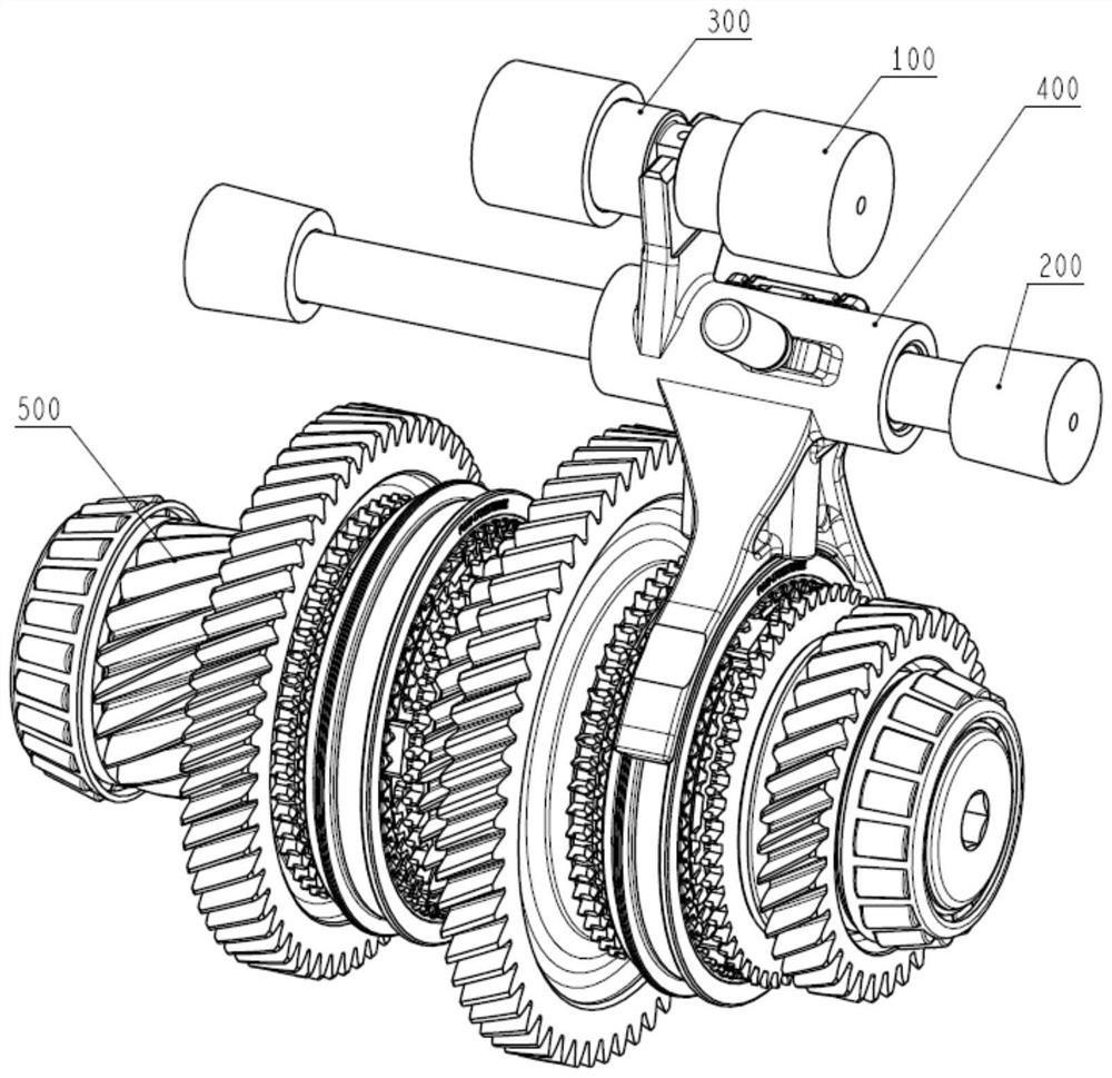
[0004] At present, there are mainly two types of lubricating devices for synchronizers. The first solution is to use oil injection pipes for active lubrication of synchronizers. The second solution is to use oil collectors to collect lubricating oil splashed by gears, and then pass through holes at the bottom of the oil collectors. , drips into the synchronizer for lubrication, and its common feature is that the lubricating oil dripped from the oil injection pipe or the oil collector is easily blocked by the gear sleeve or shift fork of the synchronizer, and the lubrication effect is not good. Lubricating gears and synchronizers, so precise control of the amount of lubricating oil during shifting cannot be achieved, and the amount of lubricating oil in the drip mode is completely uncontrollable
[0005] For the above problems, no effective solution has been proposed

Method used


Image

  • Control method and control device of synchronizer lubricating system and synchronizer lubricating system
  • Control method and control device of synchronizer lubricating system and synchronizer lubricating system
  • Control method and control device of synchronizer lubricating system and synchronizer lubricating system

Examples


Embodiment Construction

[0033] In order to make those skilled in the art better understand the solutions of the present invention, the technical solutions in the embodiments of the present invention will be clearly and completely described below with reference to the accompanying drawings in the embodiments of the present invention. Obviously, the described embodiments are only Embodiments are part of the present invention, but not all embodiments. Based on the embodiments of the present invention, all other embodiments obtained by persons of ordinary skill in the art without creative efforts shall fall within the protection scope of the present invention.

[0034] It should be noted that the terms "first", "second" and the like in the description and claims of the present invention and the above drawings are used to distinguish similar objects, and are not necessarily used to describe a specific sequence or sequence. It is to be understood that the data so used may be interchanged under appropriate ...


PUM


Abstract

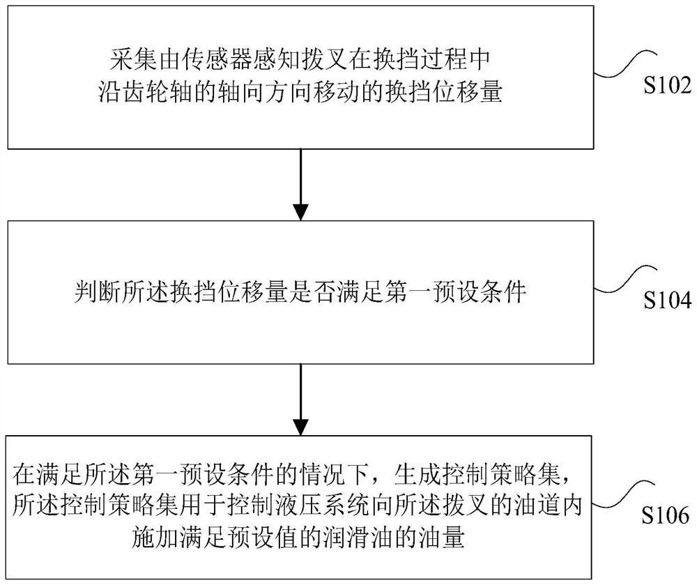
The invention discloses a control method and device of a synchronizer lubricating system and the synchronizer lubricating system. The control method comprises the steps that the gear shifting displacement, sensed by a sensor, of a shifting fork moving in the axial direction of a gear shaft in the gear shifting process of the shifting fork is collected; whether the gear shifting displacement meets a first preset condition or not is judged; and under the condition that the first preset condition is met, a control strategy set is generated, and the control strategy set is used for controlling the hydraulic system to apply the amount of lubricating oil meeting the preset value into the oil duct of the shifting fork. The technical problem that when the synchronizer is lubricated, the lubricating oil amount is uncontrollable is solved.

Description

technical field [0001] The invention relates to the technical field of lubrication system control, in particular to a control method, a control device and a synchronizer lubrication system of a synchronizer lubrication system. Background technique [0002] As the core subsystem of the transmission, the synchronizer uses the principle of friction to synchronize the speed of the gears when the transmission is shifting, which structurally ensures that the gear sleeve to be meshed and the engaging teeth cannot be in contact before synchronization is achieved, avoiding inter-tooth impact and noise. , so as to achieve rapid and smooth shifting of the transmission. According to the movement process of the synchronizer sleeve, the gear shifting process can be divided into 7 stages: free sliding before pre-synchronization, pre-synchronization, synchronization, synchronization unlocking, free sliding after synchronization, setting the engaging teeth, and full meshing. [0003] The sy...

Claims


Application Information

Patent Timeline
Patent Type & Authority Applications(China)
IPC IPC(8): F16H57/04F16D23/02
CPCF16H57/0478F16H57/0456F16D23/02
Inventor 赵雪松白秀超张成赵健涛刘君祺付超刘彦超杨阳杨永刚张小波
Owner CHINA FIRST AUTOMOBILE
Learn More