Device for dehydrating veneer

A technology of single plate and rotating plate, which is applied in the direction of drying gas arrangement, progressive dryer, and drying of solid materials without heating. stagnant effect

Active Publication Date: 2022-07-05
江西益佳木业有限公司
View PDF5 Cites 0 Cited by
  • Summary
  • Abstract
  • Description
  • Claims
  • Application Information

AI Technical Summary

Problems solved by technology

[0005] In order to overcome the shortcomings of existing drying devices that cannot automatically load materials without manual operation, the technical problem of the present invention is to provide a device for veneer dehydration that can automatically complete intermittent feeding to ensure dehydration efficiency

Method used


Image

  • Device for dehydrating veneer
  • Device for dehydrating veneer
  • Device for dehydrating veneer

Examples


Embodiment 1

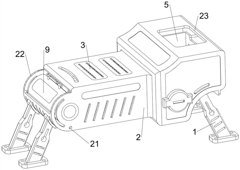
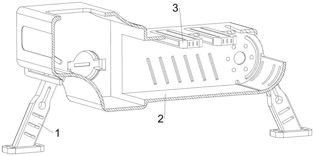
[0036] A device for dehydration of veneers, in Figure 1-3 As shown in the figure, it includes a support rod 1, a protective frame 2, a fan 3, a conveying mechanism 4 and a feeding mechanism 5. The left and right sides of the lower part of the protective frame 2 are symmetrically provided with a supporting rod 1 in the front and rear, and the left side of the top of the protective frame 2 is provided with two A fan 3 capable of drying the veneer, the top right side of the protective frame 2 is provided with a feeding chute 23 for people to put the veneer in, the left side wall of the protective frame 2 is provided with a discharging chute 22, the left side of the protective frame 2 is provided with There are card slots 21 on both sides. The protective frame 2 is provided with a conveying mechanism 4 capable of conveying veneers. A feeding mechanism 5 capable of intermittently pushing veneers is connected between the conveying mechanism 4 and the inner right side of the protecti...

Embodiment 2

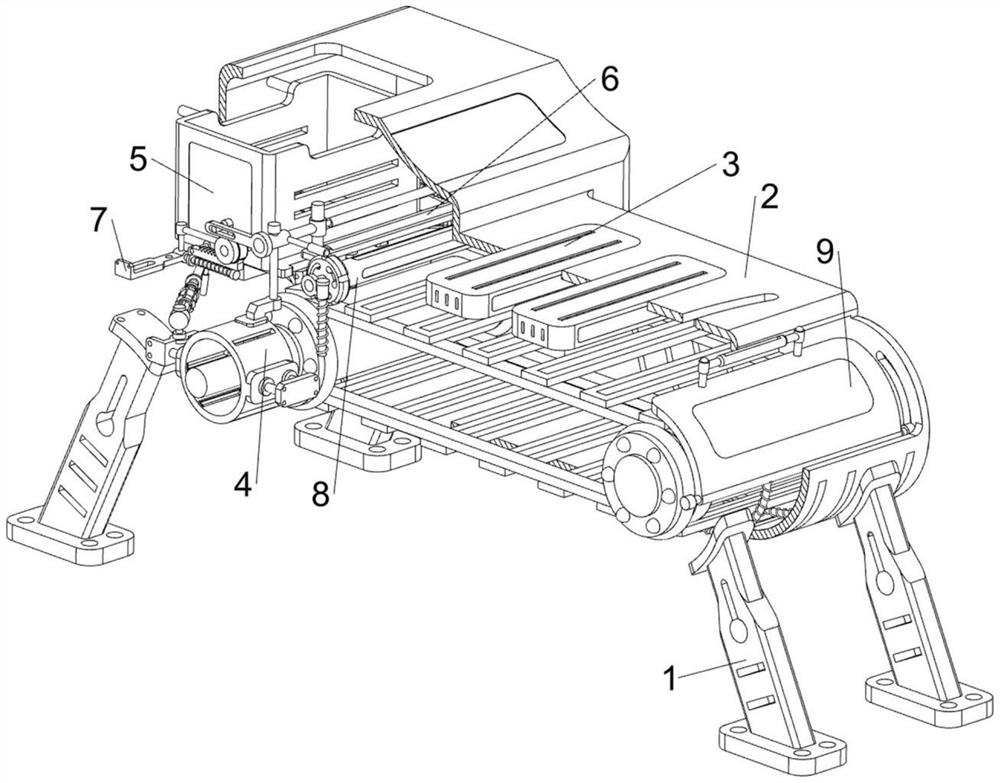
[0041] On the basis of Example 1, in figure 2 , Figure 7 and Figure 8 It also includes a wiping mechanism 6. The wiping mechanism 6 includes a guide rod 60, a connecting rod 61, a sponge plate 62 and a return spring 63. The tops of the two support frames 40 are provided with guide rods 60, and two guide rods 60. A connecting rod 61 is slidably provided between the upper side, the bottom of the connecting rod 61 is slidably provided with a sponge plate 62 capable of preliminarily dehydrating the veneer, and a return spring is connected between the front and rear sides of the sponge plate 62 and the interior of the connecting rod 61 63.

[0042] exist figure 2 , Figure 9 and Figure 10 It also includes a transmission mechanism 7, and the transmission mechanism 7 includes a second connecting block 70, a protective frame 71, a connecting shaft 72, a cam 73, a rotating rod 74, a gear 75, a limit rod 76, a rack 77, a return force The spring 78 and the toggle lever 79 are ...


PUM


Abstract

The invention relates to a dewatering device, in particular to a device for dewatering a veneer. The invention provides the device for dehydrating the veneer, which can automatically finish intermittent feeding to ensure the dehydration efficiency. A device for dewatering veneers comprises supporting rods, a protection frame, a clamping groove, a discharging groove, a discharging groove, fans, a conveying mechanism and the like, the supporting rods are symmetrically arranged on the left side and the right side of the lower portion of the protection frame front and back, the two fans are arranged on the left side of the top of the protection frame and can dry and dewater the veneers, and the discharging groove is formed in the right side of the top of the protection frame. A discharging groove is formed in the left side wall of the protection frame, clamping grooves are formed in the front side and the rear side of the left side of the protection frame, and a conveying mechanism is arranged in the protection frame. Veneers are stacked in the loading frame, the pushing block can intermittently push the veneers to the conveying belt through operation of the electric push rod, then the purpose of intermittent feeding is achieved, repeated feeding is not needed, and the loading frame only needs to be filled with the veneers at a time.

Description

technical field [0001] The present invention relates to a dehydration device, in particular to a dehydration device for veneer. Background technique [0002] Veneer refers to the wood material obtained by rotary cutting or slicing, with a thickness of about 1 mm, which is used to manufacture plywood and other man-made boards. At this time, the veneer needs to be dehydrated to ensure the firm bonding of the adhesive. [0003] The publication number is CN215373234U, the application number is CN202121815185.3, a veneer drying device based on plywood production, including a horizontally placed base and a drying device for drying, the drying device includes a plurality of set plates arranged on the base A slot, a number of ventilation holes arranged on both sides of the plate slot, a ventilation silo arranged on one side of the base, two fans arranged on one side of the ventilation silo, an outlet pipe arranged on one side of the ventilation silo, and an air outlet arranged at o...

Claims


Application Information

Patent Timeline
Patent Type & Authority Applications(China)
IPC IPC(8): F26B15/18F26B21/00F26B5/14F26B5/16F26B25/00F26B25/02F26B25/04
CPCF26B15/18F26B21/004F26B5/14F26B5/16F26B25/004F26B25/02F26B25/04Y02P70/10
Inventor 张从武
Owner 江西益佳木业有限公司
Why Eureka
Try Eureka