Rust-proof treatment device for steel fibers

A technology of anti-rust treatment and steel fiber, which is applied to the device and coating of the surface coating liquid, which can solve the problems of uneven dipping and low work efficiency

Active Publication Date: 2021-09-10
致泰科技新材料(江苏)有限公司
View PDF8 Cites 0 Cited by
  • Summary
  • Abstract
  • Description
  • Claims
  • Application Information

AI Technical Summary

Problems solved by technology

[0004] In order to overcome the disadvantages of low work efficiency and easy uneven dyeing due to manual operation, the technical problem to be solved is to provide a steel fiber anti-rust coating that does not require manual operation, has high work efficiency, and can be uniformly dyed. processing device

Method used


Image

  • Rust-proof treatment device for steel fibers
  • Rust-proof treatment device for steel fibers
  • Rust-proof treatment device for steel fibers

Examples


Embodiment 1

[0084] A rust-proof treatment device for steel fibers, such as Figure 1-3 As shown, including a base 1, a first support frame 2, a servo motor 3, a storage basket 4, a sheet 5, a baffle 6, a separator 7, a leak 13, a transmission mechanism 9, and a unit 10, a base 1. A first support frame 2 is provided on the left side of the top, and the lower portion of the first support frame 2 and the base 1 are provided with a servo motor 3, and there is a storage basket 4 on the top of the base 1, and a baffle is provided on the left side of the storage basket 4. 6, the storage basket 4 is slidably provided with a sheet 5, and a partition plate 7 is provided in the front side of the storage basket 4, and there is a drain network 8 on the top and rear side of the top and rear of the sheet 5. The servo motor 3 and the first support A transmission mechanism 9 is provided between the frame 2, and the opening side is provided with a dial mechanism 10 on the top of the base 1.

[0085] The staff p...

Embodiment 2

[0087] On the basis of Example 1, such as Figure 4-5 As shown, the transmission mechanism 9 includes a first spindle 90, a sleeve 91, a connecting frame 92, a first spring 93, a first gear 94, and a meshing sleeve 95, and the servo motor 3 output is provided with a first axle 90, a first spin. 90 is rotated from the first support frame 2, and the first shaft 90 is actively provided with a sleeve 91, and a connecting frame 91 is provided on the sleeve 91, and the sleeve 91 is provided with a first spring between the first support frame 2. 93, the top rotation of the sleeve 91 is provided with a first gear 94, and the first gear 94 is slidably connected to the first axis 90, and the upper rotation of the first support frame 2 is provided with a meshing sleeve 95, and the engaging sleeve 95 and the first gear 94. Compatible.

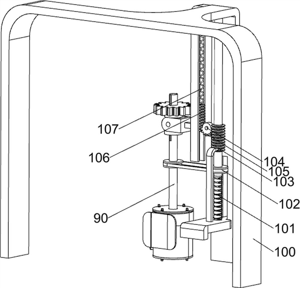
[0088] The mover mechanism 10 includes a second support frame 100, a second rotating shaft 101, a first pulley assembly 102, a rack sleeve 103, a first connect...

Embodiment 3

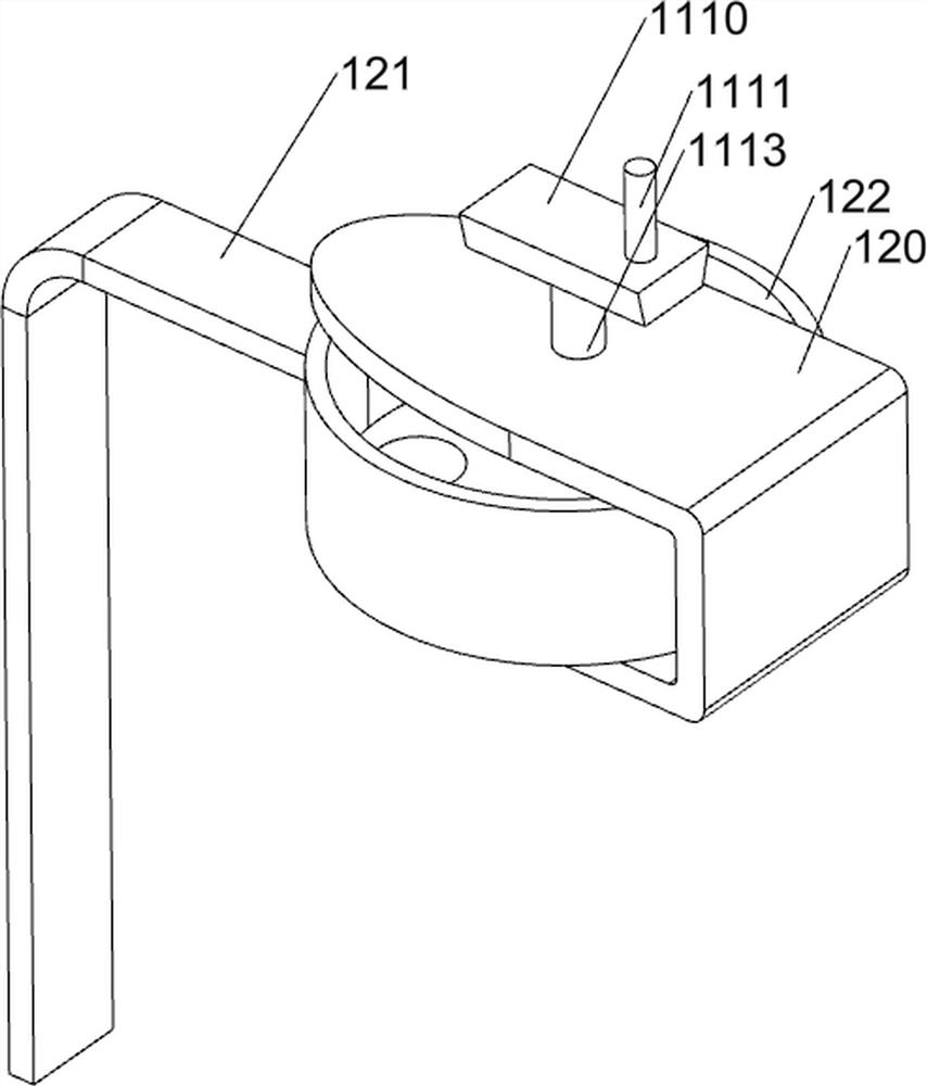
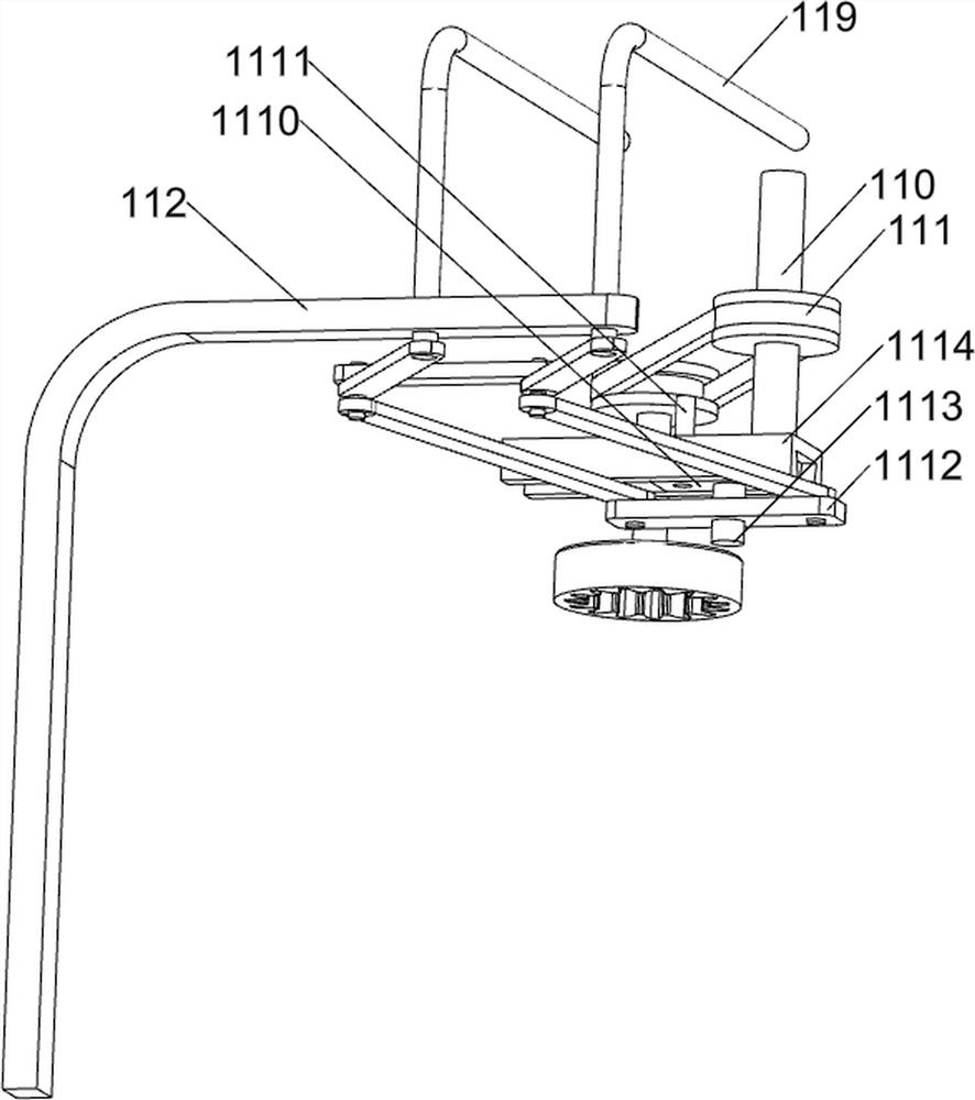
[0091] On the basis of Example 2, such as Figure 6-10 As shown, there is a rotating mechanism 11, and the rotating mechanism 11 includes a third rotating shaft 110, a second pulley assembly 111, a third support frame 112, a first connecting plate 113, a second connecting plate 114, a third connecting plate 115, The second connecting rod 116, the first sliding rail 117, the rail wheel 118, the third connecting rod 119, the slider 1110, the first guide bar 1111, the fourth connection plate 1112, the fourth connection rod 1113 and the connection block 1114, the second The top rotation of the support frame 100 is provided with the third rotating shaft 110, and the third rotating shaft 110 is provided with a second pulley assembly 111 between the transmission shaft of the engaged sleeve 95, and the second pulley assembly 111 consists of two pulley and a belt, two The pulley is connected to the transmission shaft of the third rotating sleeve 95, respectively, and the belt is disposed be...


PUM


Abstract

The invention relates to a rust-proof treatment device, in particular to a rust-proof treatment device for steel fibers. The rust-proof treatment device for the steel fibers does not need to be manually operated, is high in working efficiency and can be used for uniformly dip-dyeing. The rust-proof treatment device for the steel fibers comprises a base, a first supporting frame, a servo motor, a storage basket, a baffle, a material placing plate and a partition plate. The base is used for installing the whole device; the first supporting frame is arranged on one side of the top of the base; the servo motor is arranged between the lower part of the first supporting frame and the base; the storage basket is arranged on one side of the top of the base; the baffle is arranged on one side of the storage basket; the material placing plate is arranged in the storage basket in a sliding manner; and the partition plate is arranged on one side of the interior of the storage basket. A rotating mechanism is matched with a discharging mechanism, a transmission mechanism drives the rotating mechanism to rotate, and the rotating mechanism drives a material blocking basket to slide front and back, so that the discharging amount can be controlled, and the purpose of intermittent discharging is achieved.

Description

Technical field [0001] The present invention relates to an anti-rust treatment apparatus, and particularly to an apparatus for processing rust steel fibers. Background technique [0002] Steel fiber refers to the fine steel wire cutting method, a cold-rolled strip shear, milling or steel ingot into a rapid condensation method aspect ratio of 40 to 80 fibers. Preparation manner different outputs steel fiber properties are not the same. Although steel fibers come out soon, but the application has become increasingly widespread, more and more types. The method most rust steel fibers, steel fibers for the discharge of sodium hydroxide, sodium nitrate, a mixed aqueous solution of sodium nitrite, such that the surface is uniformly covered with steel fibers, steel fibers and the resulting homogeneous mixture and sodium hydroxide, and finally the calcium hydroxide, which mixture is thoroughly dried at a temperature of 130 ~ 150 ℃, i.e. complete rust treatment steel fibers. However, this ...

Claims


Application Information

Patent Timeline
Patent Type & Authority Applications(China)
IPC IPC(8): B05C3/15B05C11/10
CPCB05C3/15B05C11/10
Inventor 潘永凤
Owner 致泰科技新材料(江苏)有限公司
Why Eureka
Try Eureka