Concrete slump testing device for building construction

A technology for building construction and testing devices, applied in the directions of measuring devices, instruments, flow characteristics, etc., can solve the problems of high labor intensity, and achieve the effect of reducing labor intensity.

Pending Publication Date: 2022-07-05
张高
View PDF0 Cites 0 Cited by
  • Summary
  • Abstract
  • Description
  • Claims
  • Application Information

AI Technical Summary

Problems solved by technology

[0005] In order to overcome the shortcomings of the existing technology that the concrete needs to be manually filled three times and the labor inten

Method used


Image

  • Concrete slump testing device for building construction
  • Concrete slump testing device for building construction
  • Concrete slump testing device for building construction

Examples


Embodiment 1

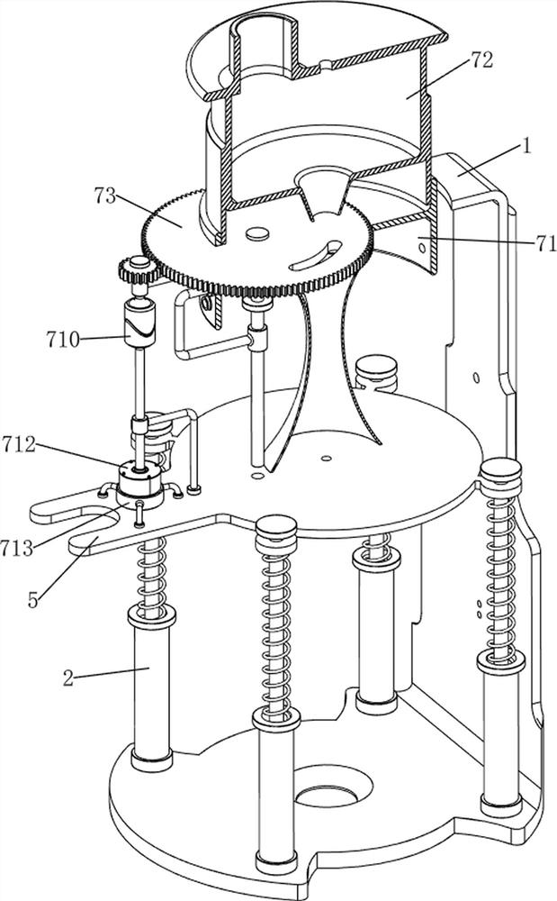
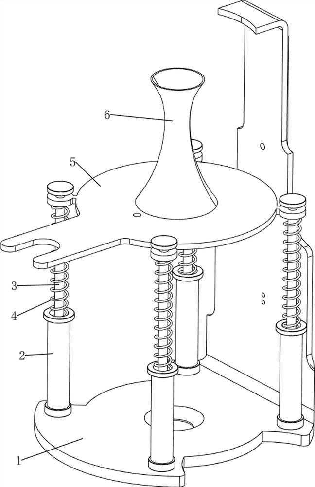
[0035] A construction concrete slump test device, refer to Figure 1-6, including a support frame 1, a support sleeve 2, a first sliding rod 3, a first linear spring 4, a support plate 5, a test cylinder 6, a blanking mechanism 7 and a fixing mechanism 8, and the lower side of the support frame 1 is provided with four The support sleeve 2, the inner side of the support sleeve 2 is slidably provided with a first sliding rod 3, the upper part of the first sliding rod 3 is provided with a support plate 5, and a first linear spring is connected between the support sleeve 2 and the support plate 5 4. A test cylinder 6 for concrete testing is placed on the top of the pallet 5, a blanking mechanism 7 for realizing automatic intermittent unloading is provided between the upper part of the support frame 1 and the pallet 5, and a lower part of the support frame 1 and the pallet 5 are provided. There is a fixing mechanism 8 for limiting the pallet 5, and the upper part of the support fra...

Embodiment 2

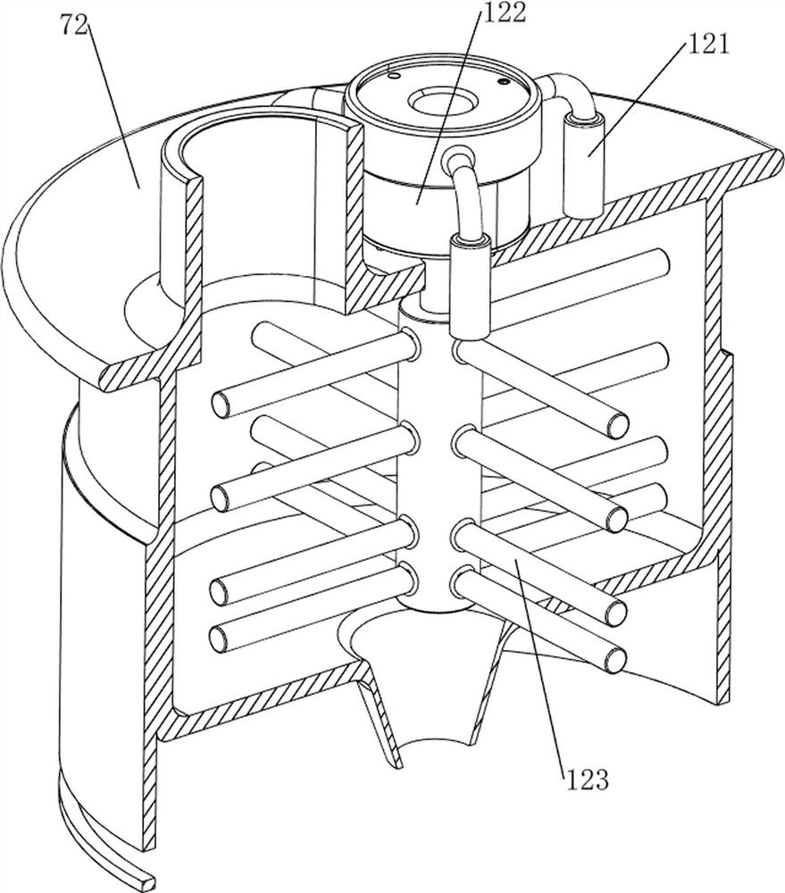
[0040] On the basis of Example 1, refer to figure 2 and Figure 7 , and also includes an emptying mechanism 9 for discharging the air in the concrete. The emptying mechanism 9 includes a fifth rotating shaft 91, a limit ring 92, a sixth rotating shaft 93, a flat belt 94, a seventh rotating shaft 95 and an emptying rod 96 There is a limit ring 92 in the middle of the support plate 5, the inner side of the limit ring 92 is rotatably provided with a fifth rotating shaft 91, the upper part of the fifth rotating shaft 91 is located in the second rotating shaft 76 and is slidably connected, and the bottom of the fifth rotating shaft 91 is provided with a sixth rotating shaft 91 Rotating shaft 93, a seventh rotating shaft 95 is rotatably provided in the middle of the right side of the pallet 5, a flat belt 94 is wound between the seventh rotating shaft 95 and the sixth rotating shaft 93 through a pulley, and the upper part of the seventh rotating shaft 95 is provided with an emptyin...


PUM


Abstract

The invention relates to a testing device, in particular to a concrete slump testing device for building construction. The invention provides a building construction concrete slump testing device capable of reducing manual labor intensity. A building construction concrete slump testing device comprises a supporting frame, supporting sleeves, first sliding rods, first linear springs, a supporting plate, a testing cylinder, a discharging mechanism and the like, the four supporting sleeves are arranged on the lower side of the supporting frame, the first sliding rods are arranged on the inner sides of the supporting sleeves in a sliding mode, and the supporting plate is arranged between the upper portions of the first sliding rods; first linear springs are connected between the supporting sleeves and the supporting plate, a testing cylinder used for concrete testing is placed at the top of the supporting plate, and a discharging mechanism for achieving automatic intermittent discharging is arranged between the upper portion of the supporting frame and the supporting plate. According to the concrete three-time filling device, through rotation of the first straight gear, a discharging opening is aligned with a discharging opening of a cement cylinder for three times, three-time filling of concrete is achieved, in this way, people do not need to manually fill the concrete for three times, and the labor intensity of workers is reduced.

Description

technical field [0001] The invention relates to a testing device, in particular to a building construction concrete slump testing device. Background technique [0002] In construction sites and laboratories, slump tests are usually used to determine the fluidity of mixtures, supplemented by intuitive experience to evaluate cohesion and water retention. The slump is a quantitative index to measure the level of its degree, which is used to judge whether the construction can be carried out normally. The slump cylinder of the general test device cannot be well fixed. [0003] Patent publication number CN214622649U discloses a concrete slump testing device for building construction, which relates to the technical field of slump testing. The invention includes a bearing device, a fixing device, a measuring device, a detection device and an adjustment device. The device is connected, the side surface of the bearing device is connected with the fixing device, the lower surface of ...

Claims


Application Information

Patent Timeline
IPC IPC(8): G01N33/38G01N11/00
CPCG01N33/383G01N11/00
Inventor 张高
Owner 张高
Why Eureka
Try Eureka